EasyManua.ls Logo

CAME ZE5 - User Manual

CAME ZE5
24 pages
Print Icon
To Next Page IconTo Next Page
Loading...
CONTROL PANEL
FOR EMEGA SERIES
En
g
lish
E
N
Installation manual
ZE5
319T92EN
Question and Answer IconNeed help?

Do you have a question about the CAME ZE5 and is the answer not in the manual?

Summary

CAME ZE5 Installation Manual

Control Panel for EMEGA Series

Overview of the control panel designed for EMEGA series automation units.

Product Description and Usage

Legend

Explains symbols used in the manual for clarity and safety.

General Description

Details the control panel's features, power, and functions for automation units.

Destination and Prohibited Use

Specifies the intended application for EMEGA automation units and prohibits other uses.

Limits of Use

Defines the maximum power limitations for connected motors to ensure safe operation.

Technical Specifications

Technical Data

Presents key technical parameters including power supply, load capacity, and operating temperature.

Physical Dimensions

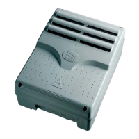
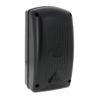
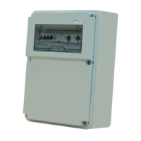
Provides physical dimensions and layout of the control panel unit.

Main Components Identification

Component List

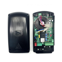
Identifies and lists all main components of the control panel for easy recognition.

Terminal Board Layout

Illustrates the layout of various terminal boards and their connections.

Installation Procedures

Preliminary Installation Checks

Essential checks before installation, including mounting surface, power source, and wiring insulation.

Required Equipment and Materials

Lists necessary tools and materials for safe and compliant installation.

Cabling Requirements

Cable Thickness and Type Specifications

Details minimum cable thicknesses and types required for various connections based on length.

Mounting the Control Panel

Anchoring and Installation

Instructions on how to anchor and install the control panel box securely.

Electrical Wiring

Gearmotor Connection

Wiring diagram for connecting the 230V AC single-phase gearmotor.

Power Supply Connection

Diagram for connecting the 230V AC power supply to the control panel.

24 V Accessory Power

Connection terminals for powering 24V accessories with power limits.

Signalling and Lighting Devices

Flashing Light Connection

How to connect a flashing light for gate open/close indication.

Gate Open Warning Light; Electric Lock

Configuration for gate open warning light or electric lock using Dip 9.

Courtesy Lamp Connection

Wiring for a courtesy lamp that illuminates the parking area.

Safety Devices Integration

Reopening Contact (NC)

Input for safety devices like photocells for reopening during closing.

DIP Switch for Safety Device

Setting DIP-switch 7 for unused safety device inputs.

Command Inputs

Stop Button Connection

Wiring for a stop button to halt gate movement and exclude auto-closing.

Key Switch; Opening Button

Connection for key switches or buttons for gate opening commands.

Sustained Action Command

Using key switches for 'sustained action' function via Dip 6.

Encoder and Limit Setup

Encoder Programming Procedure

Steps to adjust the micro-switch for encoder programming during opening.

Setting the Closing End-Stop

Procedure to set the closing end-stop using Dip-switch 8.

End-Stop Programming

Memorising Close End-Stop

Instructions to memorize the 'close' end point using the control panel buttons.

End-Stop Programming

Memorising Open End-Stop

Procedure to memorize the 'open' end point using the control panel buttons.

Slowing;Thrust Reduction Function

Notes on deactivating slowing and inserting thrust reduction via key press.

End-Stop Programming

Resetting Dip-Switch 8

Instruction to reset Dip-switch 8 to OFF after programming.

Programming Notes

General advice on programming order and potential issues.

Connecting Multiple Motors

Connecting Two Motors in Parallel

Instructions for connecting two motors in parallel using specific terminals.

Encoder and End-Stop for Single Motor

Connecting encoder and opening end-stop for a single motor in a dual setup.

Dip-Switch Configuration

Dip-Switch Function Settings

Detailed explanation of each DIP-switch function and its effect on operation.

Adjusting Settings

A.C.T. Trimmer

Adjusting the automatic closing time using the A.C.T. trimmer.

AMP. S Trimmer

Setting obstacle detection sensitivity with the AMP. S trimmer.

S. DELAY Trimmer

Adjusting the safety intervention time for obstacles with the S. DELAY trimmer.

Motor Torque Adjustment

Reducing Motor Torque

Procedure to reduce motor torque by moving a terminal board.

Increasing Motor Torque

Method to increase motor torque by isolating wires and adding a bridge.

Radio Command Setup

Antenna Connection

Connecting the RG58 antenna cable to the appropriate terminals.

Radiofrequency Card Installation

Installing the AF43S/AF43SM radiofrequency card and setting jumpers.

Code Memorisation

Memorising Transmitter Code

Procedure to memorize the transmitter code using the control board buttons.

Environmental and Compliance Information

Product Disposal and Recycling

Guidelines for the proper disposal and recycling of the product and its packaging.

Manufacturers Compliance Statement

Declaration of conformity with relevant EU directives and standards.

Overview

The CAME ZE5 is a control panel designed for EMEGA series garage-type door automation units (E306-E456) with either double or single motors. It is engineered and built by Came Cancelli Automatici S.p.A. The control panel is powered by 230 V AC on terminals L and N, with a maximum frequency of 50/60 Hz. Command devices and accessories are powered by 24 V. The total power of accessories connected to the panel must not exceed 20 W. All connections are protected by quick fuses, with specific fuse ratings provided in a table: the electronic board (line) is protected by a 5 A fuse, command devices by a 630 mA fuse, and accessories by a 1.6 A fuse.

Function Description:

The ZE5 control panel provides and controls several key functions for garage door automation:

  • Automatic Closing: Activates automatic closing after an opening command. The time for automatic closing activation can be adjusted using the A.C.T. trimmer, ranging from a minimum of 1 second to a maximum of 120 seconds.
  • Maintained Action Command: Supports a maintained action command mode.
  • Command Modes: Offers various command modes including opening/closing and total stop.
  • Photocell Intervention: When photocells detect an obstacle, they can trigger either the reopening of a closing gate or a total stop.
  • Obstacle Detection Sensitivity: The sensitivity for obstacle detection during movement can be adjusted using the AMP. S trimmer (when Dip Switch 6 is OFF), allowing for more sensitive (+) or less sensitive (-) detection.
  • Automatic Safety Intervention Time: The automatic safety's intervention time (movement inversion or stop) after an obstacle is detected can be adjusted using the S. DELAY trimmer (when Dip Switch 6 is OFF), allowing for faster (+) or slower (-) response.
  • Additional Connections: The panel allows for the connection of a gate open warning lamp (or an electric lock as an alternative) and a courtesy lamp to light the parking area during an opening/closing cycle.

Technical Specifications:

  • Power Supply: 230 V - 50/60 Hz
  • Maximum Allowed Power Load: 400 W
  • Power Draw When Idle: 150 mA
  • Maximum Power Rating for 24V Accessories: 40 W
  • Container Material: ABS
  • Degree of Protection: IP54
  • Working Temperature: -20 / +55 °C
  • Overall Motor Power: Must not exceed 300 W (or 400 W, as indicated in the manual).

Dimensions:

  • Height: 225 mm
  • Width: 115 mm
  • Depth: 87 mm (main body), 46 mm (mounting bracket)
  • Mounting hole spacing: 180 mm (vertical), 75 mm (horizontal)

Minimum Thicknesses and Cable Types:

The manual provides a table for minimum cable thicknesses based on cable length (1-10m, 10-20m, 20-30m) for various connections:

  • 230V 2F Power Supply: 3G 1.5mm² (1-10m), 3G 2.5mm² (10-20m), 3G 4mm² (20-30m)
  • 230V 2F Motors: 4G 1mm² (1-10m), 4G 1.5mm² (10-20m), 4G 2.5mm² (20-30m)
  • 230V Flashing Lamp: 2 x 0.5mm² (1-10m), 2 x 1mm² (10-20m), 2 x 1.5mm² (20-30m) - FROR CEI 20-22
  • 230V Cycle / Courtesy Lamps: 3G 0.5mm² (1-10m), 3G 1mm² (10-20m), 3G 1.5mm² (20-30m) - FROR CEI 20-22
  • Power for 24V Accessories: 2 x 0.5mm² (1-10m), 2 x 0.5mm² (10-20m), 2 x 1mm² (20-30m) - CEI EN 50267-2-1
  • 24V Pilot Lamp: 2 x 0.5mm² (1-10m), 2 x 0.5mm² (10-20m), 2 x 1mm² (20-30m) - CEI EN 50267-2-1
  • Safety Contacts: 2 x 0.5mm² (all lengths) - CEI EN 50267-2-1
  • N.O./N.C. Command Keys: 2 x 0.5mm² (all lengths) - CEI EN 50267-2-1
  • End-Stop: 2 x 0.5mm² (1-10m), 2 x 1mm² (10-20m), 2 x 1.5mm² (20-30m) - CEI EN 50267-2-1
  • Aerial Connection: RG58 - max. 10 m
  • Encoder Connection: Shielded cable 2402C 22AWG - max. 5 m

Usage Features:

  • Dip-Switch Functions: The panel features 10 dip-switches to configure various operational parameters:
    • Dip 1 ON: Automatic closing activated.
    • Dip 2 ON: "Open-stop-close-stop" command mode with key (2-7) and radio remote control (AF board inserted).
    • Dip 2 OFF: "Open-close" command mode with key (2-7) and radio remote control (AF board inserted).
    • Dip 3 ON: "Opening only" with radio remote control (AF board inserted).
    • Dip 4 ON: Pre-flashing during opening and closing phases activated (flashing lamp on W-E1 flashes for 5 seconds before command execution).
    • Dip 5 ON: Obstacle detection activated (prevents movement if safety devices detect an obstacle when motor is stopped).
    • Dip 6 ON: Reduces automatic safety intervention speed after obstacle detection, excludes closing deceleration, and activates closing thrust (AMP S and DELAY S trimmers excluded).
    • Dip 7 OFF: Reopening during closure activated (safety device 2-C1 detects obstacle during closing, door inverts movement until fully open).
    • Dip 8 ON: Encoder programming activated (enables opening and closing end-stop calibration).
    • Dip 9 ON: "Door Open" pilot light connected on terminals 10-5 activated (signals open position, switches off when door is closed).
    • Dip 9 OFF: Electric lock connected to terminals 10-5 activated.
    • Dip 10 ON: Motor closing thrust increase activated.
    • Dip 5-10 ON: Increased thrust during closing and surge function in operation.
  • Encoder Programming: Involves adjusting the stop micro-switch during opening and setting the closing and opening end-stops. This process requires setting dip-switch 8 to ON, pressing "CLOSE" to fully close the door, then pressing "OP/CL" to memorize the close end-point, and finally pressing "CH1/OP" to fully open the door and pressing "OP/CL" again to memorize the open end-stop.
  • Motor Torque Adjustment: The motor torque can be adjusted by moving the "A" terminal board connector to "B" to reduce torque, or by isolating black and brown wires and inserting a bridge as shown in the diagram to increase torque.
  • Radio Command Activation: Involves connecting an RG58 antenna cable, positioning a jumper on AF43S/AF43SM radiofrequency cards (depending on transmitter series), and plugging in the radio-frequency card onto the electronic board after cutting off the main power supply.
  • Code Memorization: Codes are memorized by pressing and holding the "CH1/OP" key until the LED indicator flashes, then sending the code via a transmitter key. The LED will remain lit to confirm memorization.

Maintenance Features:

  • Fuse Protection: All connections are protected by quick fuses, which can be replaced if necessary according to the provided fuse table.
  • Troubleshooting: The LED indicator provides feedback during encoder programming; if it flashes rapidly after resetting dip 8, the programming procedure needs to be repeated.
  • General Notes: During programming, it is crucial to memorize the closing end-stop first, otherwise, the data will not be retained.

Installation Requirements:

Before installation, ensure the mounting point is free from impacts, solid, and that proper tools and materials are used. An omnipolar cut-off device with contacts greater than 3 mm and sectioned power source must be set up. Internal connections for the protective circuit must have extra insulation. Proper conduits and electric cable raceways, protected from mechanical damage, must be used.

Environmental Compliance:

CAME Cancelli Automatici S.p.A. operates under an ISO 14001 certified Environmental Management System. Packaging components (cardboard, plastic, etc.) are recyclable as urban solid waste. Product components (aluminum, plastic, iron, electrical cables) are also recyclable. Electronic boards and radio control batteries may contain pollutants and should be disposed of by authorized companies. Always verify local regulations for waste disposal.

CAME ZE5 Specifications

General IconGeneral
BrandCAME
ModelZE5
CategoryControl Panel
LanguageEnglish

Related product manuals