Do you have a question about the CAME ZM3ES and is the answer not in the manual?
Describes the purpose and allowed usage of the ZM3ES control panel for swing gates.
Lists the fuse types and ratings for the control board, accessories, and E.LOCK.
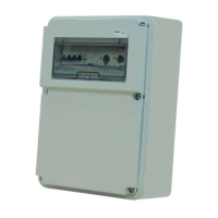
Provides physical measurements of the control panel enclosure in millimeters.
Ensures proper anchoring, power supply, internal connections, and cable protection before installation.
Confirms availability of necessary tools and materials for safe and compliant installation.
Details required cable types and minimum sizes for various electrical connections.
Provides a guide for mounting the control panel and routing electrical wires.
Details wiring for powering 24V AC/DC accessories and 12V electrolock.
Explains how to connect 400V AC gearmotors with delayed action.
Covers connections for signal flashers, courtesy lights, and open-gate indicator lights.
Details NC contact configuration for photocells (C1-C4) and their operational logic.
Details NC contact configuration for sensitive edges (C7-C8) and their operational logic.
Explains how to test the functionality of safety devices like photocells via the control board.
Details the serial connection using RSE card and UTP CAT 5 for home automation via CRP.
Explains the use of ESC, <, >, ENTER keys and display symbols for programming.
Configure AutoClose waiting time and Obstacle Detection behavior for safety.
Set up Maintained Act, Total Stop, and input configurations for CX, CY, CZ safety devices.
Configure Preflashing, Ram Hit Function, Closing Thrust, and Lock for gate operation.
Set up general configuration (decelerations) and endstop contact types.
Configures command contacts (2-7, 2-3P), light outputs (E3), and motor/CRP settings.
Provides access to the timing adjustment menu for various operational parameters.
Set waiting times for automatic closing, pedestrian opening, and motor delays.
Adjust gearmotor cycle time, preflashing, lock release, thrust, and specific opening times.
Covers adding, modifying, and removing users, backup, and restore functions.
View software version, run counts, standby messages, and perform system reset.
Test and verify the correct rotation direction of the gearmotors.
Step-by-step guide to add a new user with a specific function and code.
Guide to change the name associated with an existing user.
Guide to change the code associated with a specific user.
Guide to assign or change the function linked to a user.
Details saving and reusing user and system configuration data with another board.
Lists common error messages displayed and their meanings for troubleshooting.
| Max motor power | 800 W |
|---|---|
| Output Type | Relay |
| Power supply | 230 V AC 50/60 Hz |
| Accessories power supply | 24V DC |
| Operating temperature | -20 ÷ +55 °C |
| Operating Voltage | 230V AC |