A B GND
R S T N
UW V
XWY
E
1
E2
26 2 3 4 5
8
9
10
11
6
7
12
16
14
15
17
19
20
21
22
23
13
18
24
25
1
Page
3 - Manual code:
FA00321-EN vers.
1 02/2017 © CAME S.p.A. - The data and information shown in this manual are to be considered subject to change at any time and without the need for any advance warning.
Tools and materials
Make sure you have all the tools and materials you need for installation at hand to work in complete safety and compliance with the current
regulations. The following figure shows some basic equipment needed by the installer.
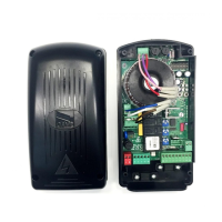
Description of parts
1. Main switch
2. Cut-off switch
3. Power meter
4. Safety switch for 1st motor
5. Safety switch for 2nd motor
6. Transformer 230-24V
7. Terminal for connecting gearmotors and flashing light
8. Opening remote control switch for 1st motor
9. Closing remote control switch for 1st motor
10. Opening remote control switch for 2nd motor
11. Closing remote control switch for 2nd motor
12. Card fuse
13. Accessories fuse
14. Electrolock fuse
15. Display
16. Display lighting adjustment trimmer
17. Memory roll card connector
18. AF card connector
19. R700 card connector
20. Warning LED / open contact error
21. Programming buttons
22. Connection terminal board
23. Voltage signalling LED
24. RSE card connector
25. Terminal board for antenna
26. Terminal board for power supply
GENERAL INSTALLATION INFORMATION
⚠
Installation must be carried out by expert qualified personnel and in full compliance with the regulations in force.
⚠
Before working on the control panel, disconnect the mains power and remove the batteries, where present.
Preliminary checks
⚠
Before installing the control panel:
• Check that the panel anchoring point is protected from possible knocks, and that the anchoring surface is solid. Also check that appropriate
screws, plugs, etc. are used to anchor the panel;
• Make sure that the power supply network is equipped with a suitable all-pole disconnection device, which provides full cut-off in category III
power surge conditions, as required by the installation regulations (i.e. contacts are more than 3 mm apart);
• Make sure that any connections inside the case (that provide continuance to the protective circuit) are fitted with extra insulation as
compared to the other conductive parts inside.
•
Make sure you have suitable tubing and conduits for the electrical cables to pass through and to protect against mechanical damage.
 Loading...