420
220
Page
4 - Manual code:
FA00321-EN vers.
1 02/2017 © CAME S.p.A. - The data and information shown in this manual are to be considered subject to change at any time and without the need for any advance warning.
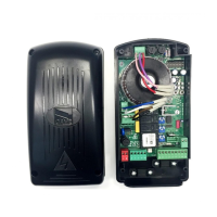
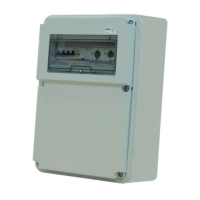
Fix the base of the control panel in a protected area using screws and plugs, or adequate supports .
Puncture the pre-drilled holes and insert the cable glands with conduits for the electric wires.
.
Pre-drilled hole diameter: 23, 29 and 37 mm.
After making the necessary adjustments, fix the cover using the screws supplied .
INSTALLATION
Types of cable and minimum sizes
Connection Type of cable
Cable length
1 < 15 m
Cable length
15 < 30 m
Control panel power supply 400 V AC
H05RN-F
4G x 1.5 mm
2
4G x 2.5 mm
2
Motor power supply 400 V AC 4G x 1.5 mm
2
4G x 2.5 mm
2
Flashing light 230 V AC 2 x 0.5 mm
2
Transmitter photocells
FROR CEI 20-22
CEI EN
50267-2-1
2 x 0.5 mm
2
Receiver photocells 4 x 0.5 mm
2
Control and safety devices 2 x 0.5 mm
2
Antenna RG58 max 10 m
Coupled connection or CRP UTP CAT5 max 1000 m
If the cable lengths di er from that specifi ed in the table, then you must determine the cable diameter based on the actual power draw from
the connected devices and according to the CEI EN 60204-1 standard.
For connections that require several, sequential loads, the sizes given in the table must be re-evaluated based on actual power draw and
distances. When connecting products that are not specifi ed in this manual, please refer to the documentation provided with said products.
 Loading...