2.0 11/2012 © CAME cancelli automatici s.p.a.
EN
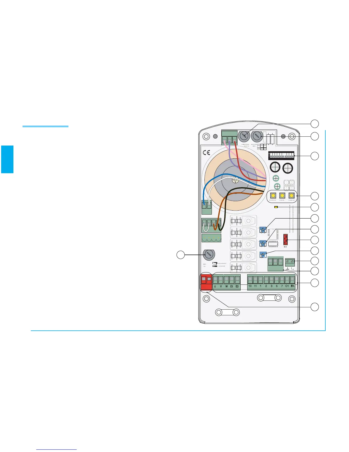
1 630 mA board fuse
2 1.6 A fuse for accessories
3 Dip-Switch for function selector
4 Keys for radio code memorisation and for end-stop
programming
5 LED indicator
6 Trimmer for adjusting automatic closing times
7 Encoder sensitivity adjustment trimmer
8 Trimmer for adjusting operation times
9 Radiofrequency board coupling
10 5 A line fuse
11 Encoder connection terminal board
12 Aerial connection terminal board
13 Connection terminal board
14 Power feed terminal board
Main Components