This document describes the CAME ZLX24, ZLJ24, and ZL19N control panels, which are used for automating gates. The manual provides detailed information on the kit components, control board layout, installation, electrical connections, programming, and various functions.
Function Description
The control panels are designed to manage the operation of gate motors, including opening, closing, and various safety and signaling functions. They support different motor types and configurations, offering flexibility for various gate automation setups. The panels integrate safety devices like photocells and sensitive edges, and can be programmed for specific operational parameters such as slowdown points, thrust, and automatic closure.
Important Technical Specifications
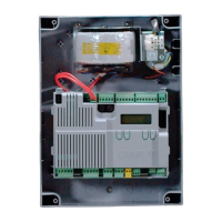
Control Board Components (ZLX24 shown as example):
- Accessories fuse: Protects accessory circuits.
- Control board fuse: Protects the main control board.
- Terminal board for power supply to the control board: Connects the main power supply.
- Terminal board for connecting the signaling devices: For flashing beacons, additional lights, and operator status warning lights.
- Terminal board for connecting control devices: For stop buttons, command inputs (open, close, partial opening), and antennas.
- Display: For programming and status indication.
- Terminal board for connecting the safety devices: For photocells (CX, CY, CZ, CK inputs) and sensitive edges.
- Memory Roll card connector: For saving and loading configuration data.
- Terminal board for B1-B2 output: Bistable or monostable output for various functions.
- Connector for CAME KEY: For advanced diagnostics and programming.
- RIO CONN card connector: For connecting RIO System wireless devices.
- Terminal board for CRP connection: For connecting CRP accessories.
- RSE card connector: For connecting RSE communication modules.
- Terminal board for connecting the antenna: For radio decoding.
- Connector for plug-in radio frequency card (AF): For integrating radio receivers.
- Programming buttons: ESC, <>, ENTER for navigating menus and setting parameters.
- Terminal board for BUS devices: For connecting CAME BUS accessories.
- Terminal boards for connecting micro limit switches and/or encoders: For precise gate positioning and slowdown control.
- Terminal board for connecting the gearmotor with encoder or with slowdown switch and electric lock: Main motor connections.
Power Supply and Output:
- Accessories output (10-11): 26 AC, 20W max.
- Additional light output (10-E3): 26 AC, 10W max.
- Flashing beacon output (10-E): 26 AC, 10W max.
- Operator status warning light output (10-5): 26 AC, 3W max.
- Auxiliary contact (B1-B2): 24V (24V AC/DC).
Fuses:
- Fuse 4 A (line 120 V)
- Fuse 3.15 A (line 230 V)
- Two 2-pole terminal blocks
Motor Power:
- Minimum power: up to 120W
- Medium power (Default): up to 200W
- Maximum power: more than 200W
Slowdown Speed:
- Opening/Closing slowdown speed: 10% to 50% (Default 40%).
Opening/Closing Speed:
- 40% to 100% (Default 70%).
Automatic Closure:
- From 1 to 180 seconds (Default 1).
- Automatic closing after either partial or pedestrian opening: Off or 1 to 180 seconds (Default 10).
M1/M2 Closing Delay Time:
- Off or 1 to 25 seconds (Default 2).
M1 Opening Delay Time:
- Off or 1 to 10 seconds (Default 2).
RSE Communication:
- CRP address: 1 to 254 (Default 1).
- RSE speed: 4800 bps, 9600 bps, 14400 bps, 19200 bps, 38400 bps (Default), 57600 bps, 115200 bps.
Usage Features
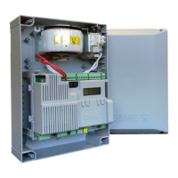
Installation:
- The control board is mounted on a support, and a fuse holder terminal block is used for power.
- Screws from the ZL19N or ZLJ24 control panel are reused for mounting.
- Electrical connections require cutting off mains power and inserting the line fuse in the terminal block.
Programming (using ESC, <>, ENTER buttons):
- ESC button: Exits menu, deletes changes, goes back to previous screen, stops the operator.
- <> buttons: Navigates menus, increases or decreases values.
- ENTER button: Accesses menus, confirms choice.
- Getting started: Electrical connections must be made, and commissioning performed by qualified staff. The full control panel manual provides information on additional functions relating to the encoder, limit switch, and slowdown switches.
- Calibration: If "CALIBRATION REQUIRED" appears, the travel must be calibrated. The panel will not accept motion commands except for the motor test.
- First maneuver: After powering up, the first maneuver is always to open the gate.
Motor Settings:
- Motor type: Generic, AXO, STYLO-ME, A3024NA/A5024N, STYLO-RME, FROG-A24, FTX, FROG-A24E (Default), FAST-70, ATS, AXI, F1024, AMICO, F4024E, FERNI, F4024EP, FERNI-V.
- Number of motors: M1+M2 (Default).
- Motor test: ">" button opens gate leaf M2, "<" button opens gate leaf M1.
- Encoder: Activated (Default) or Off.
- Reduce speed: Deactivated (Default) or 1% to 50%.
- Limit-switch function: Off, Stop in FA, stop in FC, Slowdown in FA/FC (Default), Stop in FA, slowdown in FC.
- Input type FC/FA: N.O. (Default), N.C., N.C. for FA input, N.O. for FC input.
- Travel calibration: Only with end-of-travel microswitches used.
Gate Travel Settings:
- Opening/Closing speed: 40% to 100% (Default 70%).
- Travel AST control: Deactivated (Default), Customised, Customised closing, Customised opening. Offers Maximum thrust and low obstruction sensitivity (Minimum, Average, Maximum).
- Adjusting the partial opening: 10% to 100% (Default 100%).
- Opening/Closing approach space: 0.5% to 25.0% (Default 8.0%).
- Opening/Closing slowdown point: Deactivated (Default) or 1% to 50%.
- Opening/Closing slowdown speed: 10% to 50% (Default 40%).
- Impact test: Activate test mode, Deactivate test mode.
Wired Safety Devices:
- Total stop: Deactivated (Default) or On.
- CX/CY/CZ/CK input: Configurable for various safety functions (photocells, sensitive edges, obstacle standby, reopen while closing, etc.).
- Safety devices test: Configurable for different combinations of CX, CY, CZ, CK inputs.
Command Inputs:
- Command 2-7: Step-by-step (Default) or Sequential.
Functions:
- Electric lock: Deactivated (Default), From open, From closed, Continue.
- Closing thrust: Deactivated (Default), Minimum, Medium, Maximum.
- Thrust: Deactivated (Default) or On.
- Removing obstacles: Deactivated (Default) or On.
- B1-B2 output: Bistable or Monostable (from 1 to 180 seconds, Default 1).
- Hold-to-run: Deactivated (Default) or On.
Times:
- Automatic closure: Deactivated (Default) or From 1 to 180 seconds.
- Automatic closing after either partial or pedestrian opening: Off or 1 to 180 seconds (Default 10).
- M1/M2 opening/closing delay time: Off or 1 to 10 seconds (Default 2 for M1 opening), Off or 1 to 25 seconds (Default 2 for M2 closing).
Manage Lights:
- Passage-open warning light: Warning light on (Default), Warning light flashing, Warning light flashes every half second, Warning light flashes every second.
- Additional light: Disabled (Default), Cycle lamp, Courtesy light.
- Courtesy time: 60 to 180 seconds (Default 60 seconds).
- Pre-flashing time: Deactivated (Default) or 1 to 10 seconds.
RSE Communication:
- CRP address: 1 to 254 (Default 1).
- RSE speed: Various baud rates.
External Memory:
- Save data: Saves user data and system configuration to a MEMORY ROLL card.
- Read data: Uploads user data, timings, and configurations from a MEMORY ROLL card.
Configuration:
- Parameter reset: Confirm? NO, Confirm? YES.
- Guided procedure (Wizard): For initial setup.
Manage Users:
- New user: Step-by-step, Sequential, Open, Partial opening, B1-B2 output.
- Remove user/Remove all: Confirms deletion of users.
- Radio decoding: All decoding (Default), Rolling code, TW Key block.
- Self-Learning Rolling: Deactivated (Default) or On.
- Change mode: Step-by-step, Sequential, Open, Partial opening, B1-B2 output.
Information:
- FW version: Displays firmware versions for motor board, display board, and graphics.
- Manoeuvre counter: Displays total, partial, and recent maneuvers.
- Configure maintenance: Deactivated (Default) or 1X100 to 500X100.
- Maintenance reset: Confirms maintenance reset.
- Errors list: Displays error messages.
Timer Management:
- Show clock/Set the clock: Displays and allows setting the clock.
- Automatic DST: Deactivated (Default), On (Summer changeover: +1 hour in March, Winter changeover: -1 hour in October).
- Time format: 24-hour or 12-hour.
- Create new timer: Open, Partial opening, B1-B2 output, with Start time, End time, Days of the week, Select days, All week options.
- Remove timer: 0 = [Opening], P = [Partial opening], B = [Output B1-B2].
Language:
- Italiano (IT), English (EN) (Default), Français (FR), Deutsch (DE), Español (ES), Português (PT), Русский (RU), Polski (PL), Românesc (RO), Magyar (HU), Hrvatski (HR), Український (UA), Nederlands (NL).
Password:
- Enable password/Remove password/Change password: Manages password protection.
Factory Reset:
- Disconnect control board power, wait for it to switch off. Press and hold "<" and ">" buttons, then reconnect the control board to power. Continue holding until "Factory reset" is displayed. Select "Confirm YES". Press ENTER to confirm.
- Warning: When you reset the control board, all saved users, set times, manoeuvre configurations, and calibration operations are deleted.
Import/Export Data:
- Save data: Insert MEMORY ROLL card, disconnect mains power, press "Enter" to access programming, then select "Save data".
- Read data: Insert MEMORY ROLL card, disconnect mains power, press "Enter" to access programming, then select "Read data".
- Warning: Before inserting and removing the MEMORY ROLL card, disconnect the mains power supply to the line.
Error Messages:
- E1: Motor M1 calibration error.
- E2: Motor M2 calibration error.
- E3: Encoder signal not detected error.
- E4: Service test failure error.
- E7: Operating time error.
- E9: Consecutive obstacles detected during closing.
- E10: Consecutive obstacles detected during opening.
- E11: Maximum number of obstacles.
- E12: Motor supply voltage missing or insufficient.
- E13: Limit switch input error or both limit switches open.
- E15: Incompatible transmitter error.
- E17: Wireless system communication error.
- E18: Wireless system not configured error.
- E24: BUS device communication error.
- E25: Address settings error on BUS devices.
Maintenance Features
- Configure maintenance: Allows setting a maintenance interval (e.g., 1X100 to 500X100 maneuvers).
- Maintenance reset: Resets the maintenance counter after service.
- Error messages: The system provides detailed error codes (E1-E25) to assist in troubleshooting and maintenance.
- Memory Roll card: Facilitates saving and restoring configurations, which is useful for maintenance and replacing control boards.