SECTION 2 - THEORY OF OPERATION
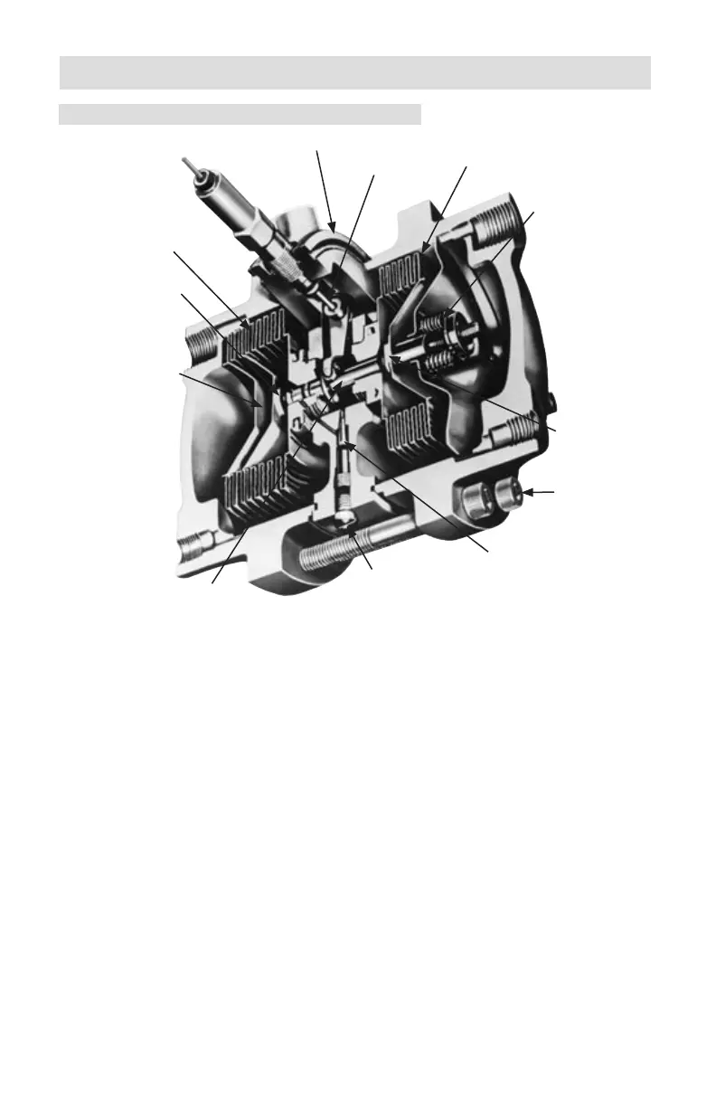
2-1. Basic Components (See Figure 2-1)
LP Housing
HP Housing
Shaft
Center Plate
Compensator
Housing
Bolts
Pulsation Damper
Torque Tube
Torque Tube
LP Bellows
Range Spring
HP Bellows
HP Over-
range Valve
Temperature
Valve Stem
LP Overrange
Valve
Damping Valve Plug
Figure 2-1. 199 BUA Cutaway
A. Pressure Housings
The two pressure housings of the Model 199 DPU are available in the vari-
ous safe working pressure ratings dened in Table 1-1 and in the Outline
Dimensional Drawings (seen in Section 6 DRAWINGS).
Each pressure housing has two tapped connection ports: one port is located
in the top of the housing, the other port is located in the bottom of the
housing.
The pressure housings may be rotated 180 degrees to facilitate connection
at the top of the housing for draining when used in gas service, or at the
bottom to provide venting when used in liquid service.
The housings enclose the bellows on each side of the center plate.
B. Bellows
The bellows of the Model 199 DPU are available in the various materials
and sizes (refer to Table 1-1) to accommodate the various safe working
pressure ratings.
The DPU has two bellows. One end of each bellows is sealed. The open
end of each bellows is attached and sealed to a side of the center plate (one
bellows on each side).
5