ENGINEERED & PROCESS VALVES
10
07/2011 / IOM-GEN-TWIN-03
Installation, Operation and Maintenance Manual
GENERAL VALVE
®
Twin Seal
™
SERIES 8800
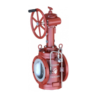
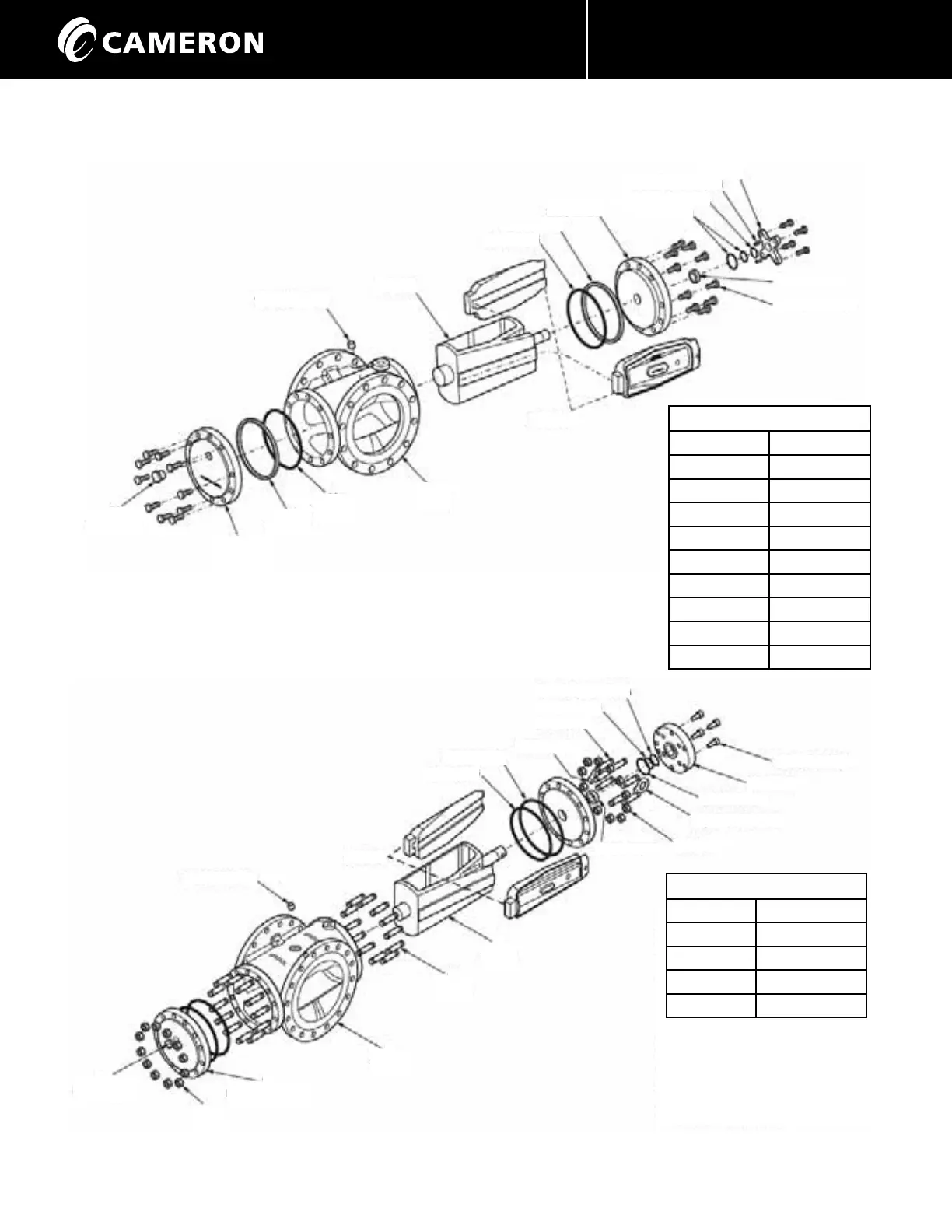
Typical Arrangement of:
2” 8851
2” 8861
3” 8851
6” 8821
8” 8811
8” 8821
10” 8811
10” 8821
12” 8811
12” 8821
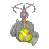
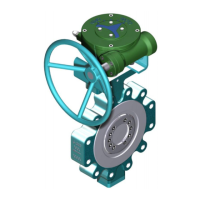
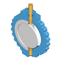
Typical Arrangement of:
14” 8811
16” 8811
18” 8811
20” 8811
24” 8811
NB: With the exception of
14”, 20” & 24” Models 8811G,
remaining sizes all incorporate
an internal coupling to connect
valve with the operator.
76 PIPE PLUG
4 PLUG
62 O-RING
49 GASKET
2 BONNET
6 GLAND
77 LOCATING PIN
62B BACKUP RING
62A O-RING
63 PACKING
72 CAP SCREW
5 SLIPS
1
BODY
62
O-RING
49
GASKET
3
LOWER
PLATE
76
PIPE PLUG
1
BODY
3
LOWER PLATE
75
NUT
76
PIPE PLUG
76 PIPE PLUG
5 SLIPS
62 O-RING
49 GASKET
62B BACKUP RING
71 STUD
71 STUD
62A O-RING
62B O-RING
63 PACKING
75 NUT
75A LIFTING LUG
6 GLAND
72 CAP SCREW
4
PLUG
71
STUD
 Loading...