ENGINEERED & PROCESS VALVES
12
07/2011 / IOM-GEN-TWIN-03
Installation, Operation and Maintenance Manual
GENERAL VALVE
®
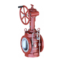
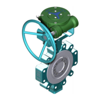
Twin Seal
™
MODEL 500H & 625H
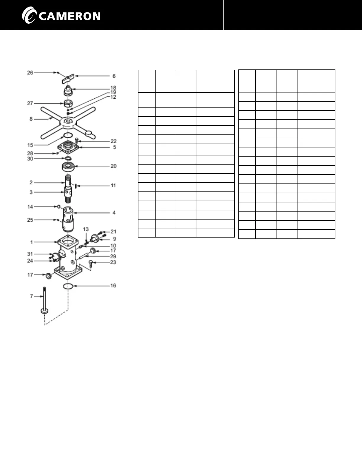
Item
No.
500 H
Part
No.
625 H
Part
No.
Description
1 21-411 21-407 Operator
Housing
2 22-408 22-411 Upper Stem
3 41-405 41-406 Drive Pin*
4 22-409 22-413 Lower Stem
5 26-408 26-405 Housing Cap
6 27-406 27-406 Indicator Flag
7 27-404 27-438 Indicator Shaft
8 28-409 28-401 Handwheel
9 41-403 41-403 Guide Pin
10 41-404 41-404 Detent Pin
11 45-401 45-413 Key
12 46-424 46-424 Bushing
13 47-401 47-401 Spring
14 48-401 48-403 Roller
15 62-17 62-17 O-Ring
OPERATOR DISASSEMBLY
1. Unscrew (26) and remove indicator flag (6).
2. Remove the stem protector (18).
3. Remove bearing retainer nut (27).
4. Remove the handwheel (8) and key (11).
5. Unbolt and remove the housing cover (5).
6. Unbolt and remove the guide pin (9), with detent pin (10) and spring (13).
7. Pull the upper stem (2) with lower stem (4), roller (14), bearing (20) and indicator shaft
(7) out through the top of the housing (1). If the bearing is snug in the housing, replace
the handwheel and key. Turn the handwheel clockwise to raise the lower stem as far as
possible. Insert a 3/8” diameter bar through the two holes in the bottom of the housing.
Turn the handwheel clockwise and jack the bearing clear of the housing.
8. Remove the set screw (16) and push the indicator shaft subassembly (7) out through the
bottom of the lower stem.
9. Remove the lower stem (4) from the upper stem (2).
10. Remove the retaining ring (30) and bearing (20) from the upper stem.
11. Remove the O-Ring (16) from the inside of the housing and grease seal (19) and bushing
(12) (if required) from the top of the upper stem (2).
Item
No.
500 H
Part
No.
625 H
Part
No.
Description
16 62-18 62-22 O-Ring
17 64-414 64-405 Plastic Plug
18 64-411 64-412 Protector
19 65-401 65-401 Grease Seal
20 66-402 66-403 Ball Bearing
21 72-4 72-4 Capscrew
22 72-5 72-6 Capscrew
23 72-6 72-11 Capscrew
24 72-21 72-21 Capscrew
25 74-1 74-3 Set Screw
26 73-28 74-6 Screw
27 75-427 75-429 Hex Nut
28 76-411 76-411 Lube Fitting
29 77-402 77-403 Coupling Pin
30 78-403 78-404 Retaining Ring
31 93-413 93-413 Cover
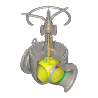
Exploded View
* not available separately.
 Loading...