ENGINEERED & PROCESS VALVES
07/2011 / IOM-GEN-TWIN-03
13
Installation, Operation and Maintenance Manual
625 H is Used on Models:
2” C851 2” C941
2” C861 4” C941
3” C851 6” C911
3” C861 6” C921
4” C841
4” C851
6” C821
8” C811
10” CA811
500 H is Used on Models:
2” C841 2” C921
3” C841 3” C911
4” C811 4” C911
4” C821 4” C921
6” CA811
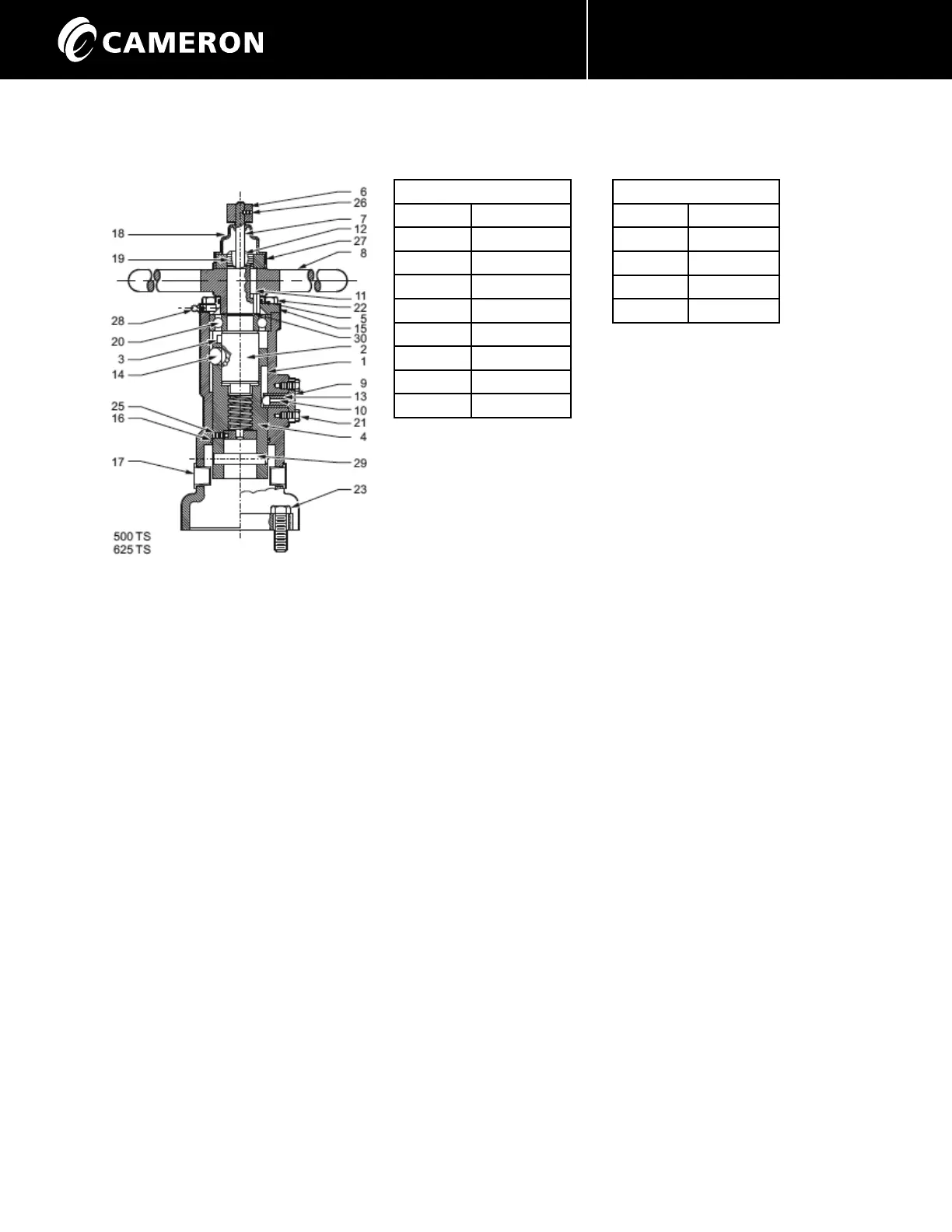
OPERATOR ASSEMBLY
1. Place the bearing (20) on upper stem (2). Install a retaining ring (30) to lock bearing in place.
2. Apply a liberal coat of grease to all surfaces of upper stem (2) below the bearing, and to all surfaces of the lower stem (4). Thread
the upper stem (2) into the lower stem (4) such that the drive pin (3) in the upper stem comes against the shoulder at the TOP
of the lower stem and the detent recess in upper stem is exactly in line with the roller opening in lower stem.
NOTE: This operation may require several attempts as the threads are multiple start and do not always assemble correctly
with the first try.
3. Install the indicator shaft assembly (7) up through both stems. Align the detent hole in the indicator disc with the threaded hole
in the lower stem and fasten with set-screw (25). Set screw must be below the outside surface of the lower stem.
4. Install O-Ring (16) in housing (1).
5. Place roller (14) in opening of lower stem. A liberal application of grease will hold it in position.
6. Place the stem assembly into the housing - taking care that roller is aligned with roller groove in housing. Push entire assembly
down until bearing rest on shoulder in housing.
7. Apply a smooth even coating of Form-a-Gasket
®
to surface of guide pin boss on housing (1).
8. Insert guide pin (14) with detent pin (10) and spring (13) to fully engage slot in lower stem and secure with capscrews (21).
9. Apply a smooth even coating of Form-a-Gasket
®
to top surface of housing (1).
10. Install O-Ring (15) in housing cover (5) and secure to housing (1) with capscrews (22).
11. Install the handwheel (8) and key (11).
12. Install the bearing retainer nut (27) and tighten securely.
13. Install grease seal (19) and bushing (12) in top of upper stem (2).
14. Install stem protector (18).
15. Install indicator flag (6) and secure with screw (26).
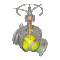
Cross Section
 Loading...