ENGINEERED & PROCESS VALVES
4
07/2011 / IOM-GEN-TWIN-03
Installation, Operation and Maintenance Manual
INSTALLATION
Orientation
Twin Seal valves may be installed in any position.
Flow Direction
The Twin Seal design is symmetrical. Flow shut-off is
achieved equally on both sides of the plug independent
of flow direction.
Note: The use of a Differential Thermal Relief (DTR) as
described on page 29 does result in a preferred
flow direction.
Clearance for Repair
For easy repair, space should be allowed below the valve for
removal of the lower plate and withdrawal of the seating
slips. See Table 1 for dimensions. Sufficient clear space is
required above the Twin Seal valve, to allow free movement
of the position indicator flag and for removal of the opera-
tor mechanism.
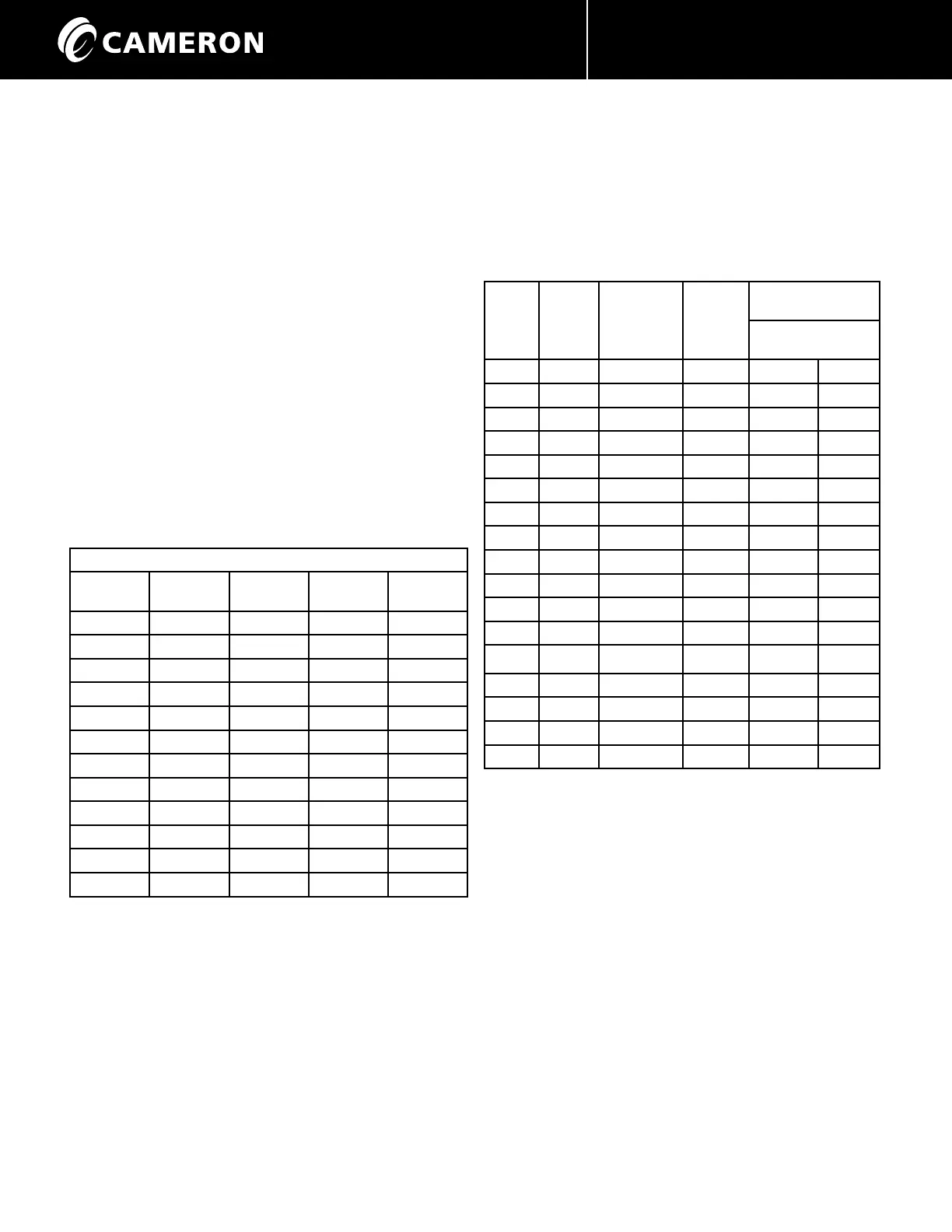
TABLE 1
Clearance required below standard ported valves for
slip removal.
Minimum Clearance
Valve Size
Inch
ASME Class
150
ASME Class
300
ASME Class
600
ASME Class
900
6” 9” 9” 10” 8”
8” 13” 11” 12” 10”
10” 15” 13” 8” 10”
12” 17” 16” 10” 10”
14” 19” 15” 10” xxxx
16” 22” 19” 14” xxxx
18” 23” 13” xxxx xxxx
20” 26” 14” 14” xxxx
24” 28” 17” 12” xxxx
28” 30” 12” xxxx xxxx
30” 30” 28” xxxx xxxx
36” 30” xxxx xxxx xxxx
Note: Allowing more than the specified minimum amount of
clearance will make servicing easier.
Flange Fasteners
Certain Twin Seal flange holes are drilled and tapped, when
there is no possibility of fitting a hexagonal nut behind the
flange. The quantity and size of these tapped holes is shown
in Table 2. Capscrews or stud bolts may be used in
these holes.
TABLE 2
Valve
Size
(inch)
ASME
Class
150
Number of
Tapped
Holes
per Flange
Thread
UNC
Length Required
(inch)
Cap Stud
Screws or Bolts
6 150 4 3/4”-10 2 1/4 3 1/4
8 150 4 3/4”-10 2 1/4 3 1/4
8300 4 7/8”-9 3 4 1/4
10 150 4 7/8”-9 2 1/4 3 1/4
10 300 4 1”-8 3 4 1/4
12 150 4 7/8”-9 2 1/4 3 1/2
12 300 4 1 1/8”-8 3 1/2 5
14 150 8 1”-8 2 1/2 4
14 600 4 1 3/8”-8 3 3/4 4 3/4
16 150 8 1”-8 2 1/2 3 3/4
18 150 8 1 1/8”-8 3 4 1/4
20 150 8 1 1/8”-8 3 4 1/2
24 150 8 1 1/4”-8 3 1/4 4 3/4
24 600 8 1 7/8”-8 5 1/4 6 3/4
28 150 6 1 1/4”-8 3 1/4 4 1/2
28 300 6 1 1/4”-8 3 1/4 4 1/2
30 150 6 1 1/4”-8 3 1/4 4 1/2
Gear Housing Orientation
On gear-operated models the gear housing and associated
hand wheel may be re-positioned as follows:
A) Place valve in fully open position.
B) Remove gear housing capscrews.
C) Turn hand wheel to further open the valve
which will turn the gear housing. Continue
until hand wheel comes to the desired position
and gear housing mounting holes are aligned.
D) Replace gear housing mounting capscrews.
NB: Short capscrew is inserted below the
worm shaft.
 Loading...