Chapter 16
16-10
16.3 Setting of Bit Switch (SSSW)
16.3.1 Outline
16.3.1.1 Bit Switch Composition
0013-1304
iR1020J / iR1024J / iR1020 / iR1024 / iR1024A / iR1024N / iR1024F / iR1024i / iR1024iF
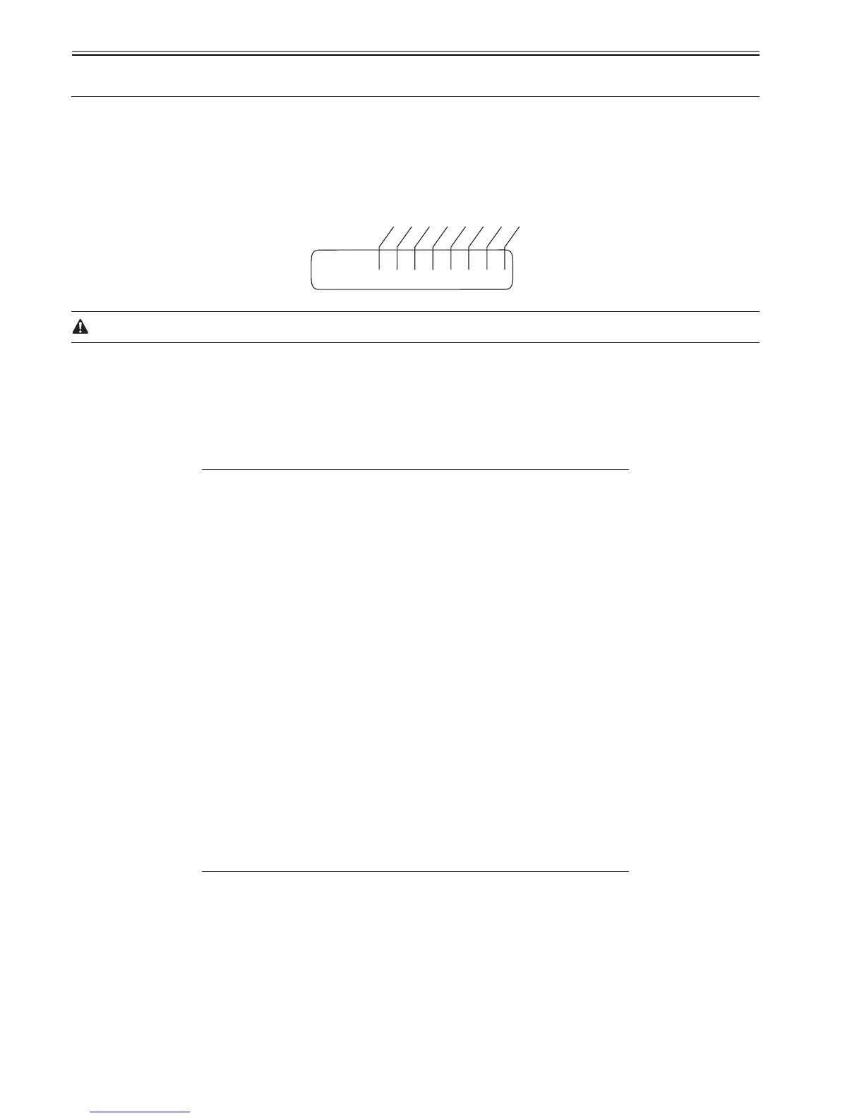
The items registered and set by each of these switches comprise 8-bit switches. The figure below shows which numbers are assigned to which bits. Each bit has a
value of either 0 or 1.
F-16-2
Do not change service data identified as "not used"; they are set as initial settings.
16.3.2 SSSW-SW01
16.3.2.1 List of Functions
0013-1305
iR1020J / iR1024J / iR1020 / iR1024 / iR1024A / iR1024N / iR1024F / iR1024i / iR1024iF
T-16-1
16.3.2.2 Detailed Discussions of Bit 0
0013-1306
iR1020J / iR1024J / iR1020 / iR1024 / iR1024A / iR1024N / iR1024F / iR1024i / iR1024iF
Selects whether or not service error codes are output.
When output is selected, service error codes is report.
16.3.3 SSSW-SW03
16.3.3.1 List of Functions
0013-1307
iR1020J / iR1024J / iR1020 / iR1024 / iR1024A / iR1024N / iR1024F / iR1024i / iR1024iF
T-16-2
Bit Function 1 0
0 service error code output not output
1 not used - -
2 not used - -
3 not used - -
4 not used - -
5 not used - -
6 not used - -
7 not used - -
Bit Function 1 0
0 not used - -
1 not used - -
2 not used - -
3 not used - -
4 not used - -
5 not used - -
6 not used - -
001
#SSSW
00000000
Bit 7
Bit 6
Bit 5
Bit 4
Bit 3
Bit 2
Bit 1
Bit 0
 Loading...