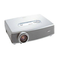
The figure on the left is a schematic diagram of the
bottom of the projector.
As shown in the figure, there are four adjustable
feet.
Adjusting the lengths of Adjustable feet 1 and 2
raises the projection direction while adjusting the
length of Adjustable feet 3 and 4 lowers the
projection direction.
Each adjustable foot can be used to make fine
adjustments to the horizontal slant of the projector.
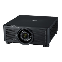
The figure on the left is a schematic diagram of the
side of the projector.
All adjustable feet are a screw-type and their
heights can be adjusted by twisting.
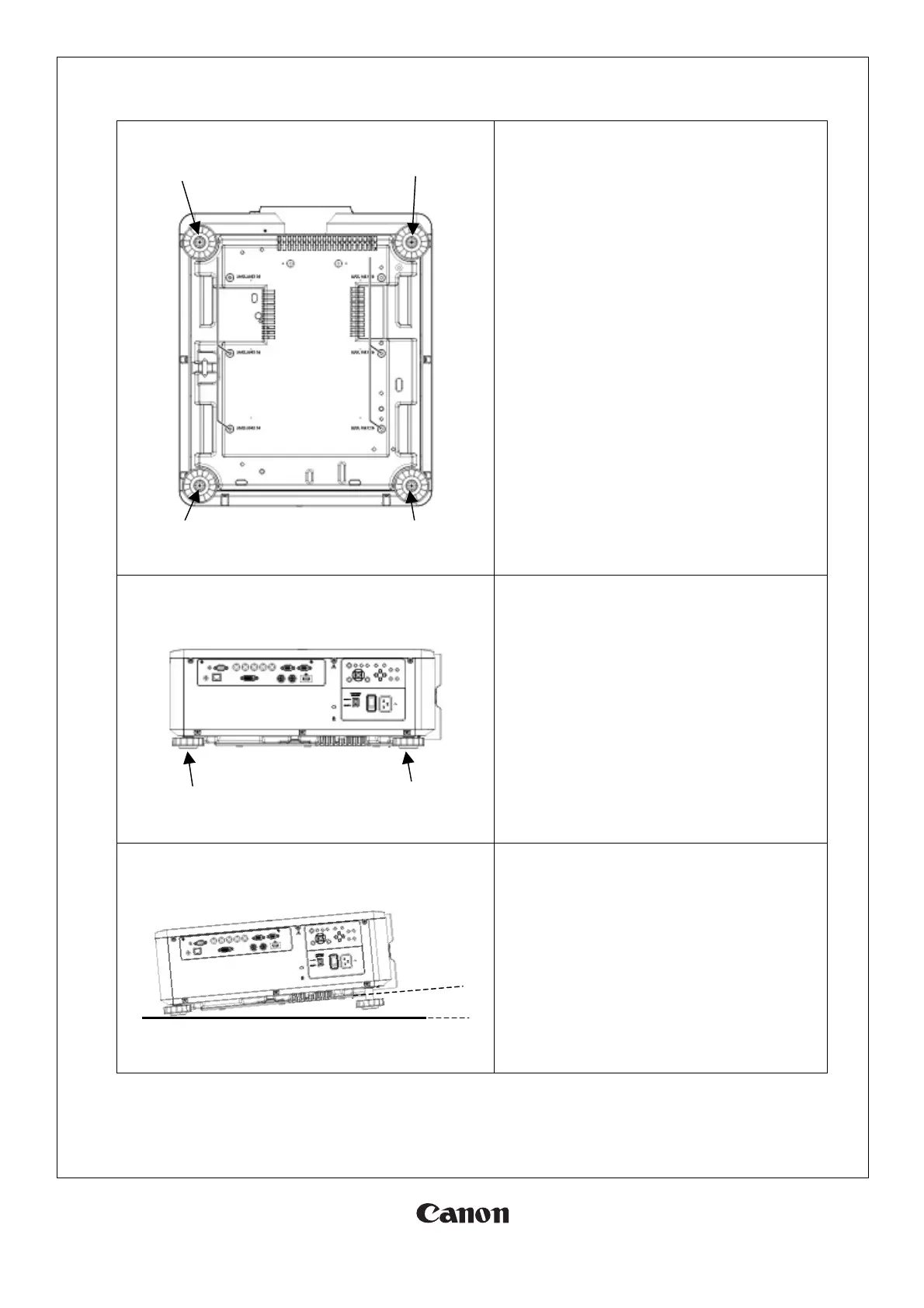
The projector can be set up at an angle of elevation
of up to 7 degrees between itself and the surface it
is placed on.
 Loading...