15
Motor connection
• Connect one of the motor phases to binding post 3 - F1; the neutral wire to binding post
4 - C; and the second motor phase to binding post 5 - F2.
• Connect the 230V power supply to binding posts 1 and 2.
• If the motor rotates in the wrong direction, invert the F1 and F2 phase wires.
Selector switch connection
• Wire a selector switch or an open close button between binding posts 7 - 8
- 9 and select the required function using dip-switch D1 as follows:
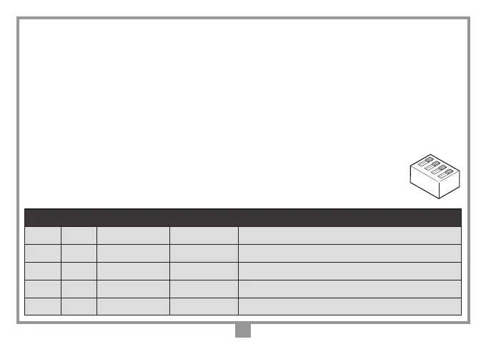
Function selection dip-switches for binding posts 7, 8 and 9
dip 1 dip 2 T1 T2 Note
OFF OFF
Open Close Default option
ON OFF
Sequential button Timer Sequential button = open - stop - close - stop
OFF ON
Open Close Dead man function only during closing
ON ON
Open Close Dead man function during opening and closing
1
2
3
4
Dip D1