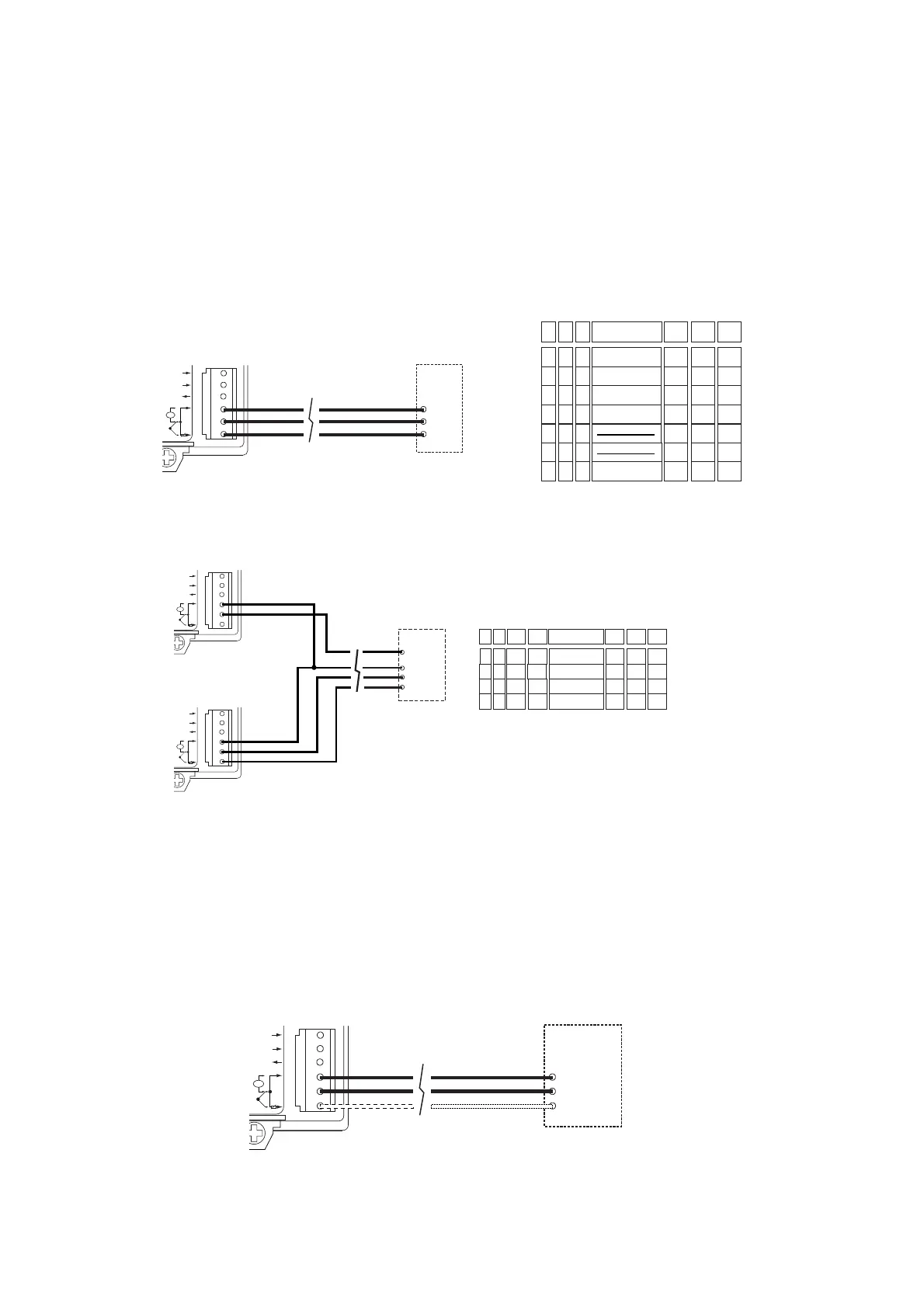
Sonde attive -1÷1/ 0÷10 Vdc
Permettono di rilevare qualsiasi grandezza fisica come temperatura,
umidità, pressione in base al tipo di sensore utilizzato. Queste sonde
possono essere remotate fino ad un massimo di 100 m purché:
• si usi del cavo schermato con la sezione dei singoli fili non inferiore a
0,5 mm
2
;
• la calza del cavo schermato sia collegata al morsetto REF del controllo
(l'eventuale schermo della sonda dovrà essere connesso alla calza
del cavo di prolunga);
• i conduttori di sonda non siano alloggiati vicino a quelli di potenza o
di comando dei teleruttori (mai nella stessa canalina);
Nel caso si collegassero due strumenti alla stessa sonda questa dovrà
essere alimentata da uno dei due strumenti (mai mettere in parallelo le
alimentazioni di due strumenti).
L'utilizzo della sonda SSD0HH10DC richiede la selezione hardware
per il segnale 0-10 Vdc (vedere par. “selezione dell’ingresso in tensio-
ne” a pag. 6).
Sonde -1÷1/0÷10 Vdc non CAREL
È possibile la connessione di tutte le sonde in commercio con segnali
-1÷1 o 0÷10 Vdc.
La predisposizione è possibile mediante la selezione dei parametri:
C05: unità di misura della grandezza rilevata;
C10: tipo di segnale: -1÷1 o 0÷10 Vdc;
C11: valore della grandezza a tensione 0 Vdc;
C12: valore corrispondente alla massima tensione: 1 o 10 Vdc.
Qualora si utilizzino sonde con segnale 0÷10 Vdc è indispensabile
predisporre l'ingresso nella scheda del CR72 per segnali 0÷10 Vdc
(vedere par. “selezione dell’ingresso in tensione”).
(*) Le sonde possono essere alimentate direttamente dal CR72 solo se
accettano alimentazione da 8 a 24 Vdc dal +V e hanno il medesimo
riferimento di alimentazione e di segnale M. La corrente assorbita non
deve superare i 40 mA.
Active probes -1÷1/ 0÷10Vdc
These permit the collection of any physical measurement such as tem-
perature, humidity or pressure, according to the type of sensor used.
These probes can be located at a distance of up to 100 meters provi-
ded that:
• screened cable with a cross-section of not less than 0.5mm
2
is used;
• the braiding of the screened cable is connected to the terminal REF
on the control unit (any screening on the probe is to be connected to
the braiding on the extension cable);
• absolutely do not introduce into the same cable ducts (included those
of the electric cables) power cables and probe cables.
Where two units are connected to the same probe, the probe must be
supplied by one or other of the two units (never connect the supplies of
two units in parallel).
Use of the SSD0HH10DC probe requires hardware selection for signal
0-10Vdc (see paragraph 3.1).
-1 to +1 and 0 to +10Vdc probes other than CAREL
All commercially available probes with signals from -1 to +1 or from 0
to +10 can be connected. Setting-up is achieved via the following para-
meters:
C05: unit of measurement of the measurement being registered
C10: type of signal: -1/+1 or 0/+10Vdc
C11: value of the measurement at voltage 0Vdc
C12: value of the measurement at maximum voltage: 1 or 10Vdc
Whenever 0-10Vdc probes are used, it is essential to set the input on
the CR72 panel for 0-10Vdc (see par. 3.1)
(*) The probes can be supplied directly from the CR72only if they
accept a supply of between 8 and 24 Vdc. from terminal +V, have the
same supply and signal M reference. Current consumed must be no
more than 40mA.
8
 Loading...


