• any joints between compensated cables are made using appropriate
connectors, as shown in the illustrations;
• compensated cables are not located near power leads or telebreaker
control leads (and never in the same conduit).
For type J thermocouples set CR72*2 at parameter C14=J.
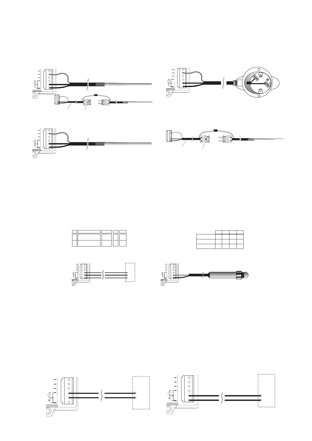
Active probes 0/20 and 4/20 mA
These supply a current signal and, according to their type, can indica-
te any measurement, such as humidity, temperature and pressure (see
table 1).These probes can be located at a distance of up to 100
meters, provided that:
• screened leads with a cross-section of not less than 0.5mm
2
are used;
• the braiding of the screened leads is connected to terminal REF on
the control unit; any screening on the probe must be connected to the
braiding of the extension cable.
• the probe leads are not laid near power or telebreaker control cables
(and never in the same conduit).
Active probes 0/20 mA and 4/20mA other than CAREL probes
It is possible to connect all commercially available probes with signals
of 0-20mA or 4-20mA; this can be set up by selecting the following
parameters:
C05: unit of measurement of the measurement being registered;
C07: type of signal: 0-20mA or 4-20mA;
C08: value of the measurement at minimum current: 0 or 4mA;
C09: value of the measurement at maximum current: 20mA.
(*) The probes can be supplied directly from the CR72 only if they will
accept a supply of between 8 and 24 Volts d.c. from terminal +V, have
the same supply and signal M reference and the current consumed is
no more than 40mA.
• per le eventuali giunzioni fra cavi compensati si utilizzino gli appositi
connettori come indicato in figura;
• i cavi compensati non siano alloggiati vicino a i cavi di potenza o vicino
ai cavi di comando dei teleruttori (mai nella stessa canalina).
Per termocoppie di tipo J selezionare sul CR72*2 il parametro C14=J
(vedere par. “Descrizione dei parametri selezionabili”).
Sonde attive 0÷20/4÷20 mA
Forniscono un segnale in corrente e possono rilevare, in base al tipo di
sensore, qualsiasi grandezza come umidità, temperatura e pressione
(vedere tab. 1). Queste sonde possono essere remotate fino ad un
massimo di 100 m, purché:
• si usi cavo schermato con la sez. dei singoli fili non inferiore a 0,5 mm
2
;
• la calza del cavo schermato sia collegata al morsetto REF del
controllo: l'eventuale schermo della sonda dovrà essere connesso
alla calza del cavo di prolunga;
• i conduttori della sonda non siano alloggiati vicino a quelli di potenza
o a i cavi di comando dei teleruttori (mai nella stessa canalina).
Sonde attive 0÷20/4÷20 mA non CAREL
È possibile la connessione di tutte le sonde in commercio con segnali
0/20 o 4/20 mA; la predisposizione è possibile mediante la selezione
dei parametri:
C05: unità di misura della grandezza rilevata;
C07: tipo di segnale: 0-20 o 4-20 mA;
C08: valore della grandezza alla minima corrente: 0 o 4 mA;
C09: valore corrispondente alla massima corrente: 20 mA.
(*) Le sonde possono essere alimentate direttamente dal CR72 solo se
accettano alimentazione da 8 a 24 Vdc dal +V, hanno il medesimo
riferimento di alimentazione e di segnale M e la corrente assorbita non
supera i 40 mA.
7
 Loading...


