24
• P07 fissa in valore assoluto il valore della banda proporzionale
utilizzabile; tale valore si intende posizionato prima e dopo SET1.
• C22 fissa, all'interno del differenziale utilizzabile P07, il punto dove
il segnale analogico è al minimo valore
• C23 analogamente a C22, fissa all'interno del differenziale P07, il
punto dove il segnale analogico è al massimo valore.
C22 e C23 sono espressi in percentuale della banda proporzionale
P07 (da -100% a +100%); valori positivi fissano questi "punti" nella
zona di P07 a destra di SET1, valori negativi si riferiscono alla zona di
P07 a sinistra di SET1.
I parametri C22 e C23 definiscono il differenziale effettivo e la logica di
regolazione, precisamente:
a. se si posiziona C22 prima di C23 il modo di funzionamento è di tipo
"direct".
b. se si posiziona C22 dopo C23 il modo di funzionamento è di tipo
"reverse".
È possibile regolare la velocità di attuazione e di spegnimento del
segnale analogico tramite i parametri P22 e P23 (vedere par.
“Descrizione dei parametri operativi” ).
Esempi:
Funzionamento "direct":
si voglia controllare, ad un valore di SET1=20,
un attuatore modulante per contenere una grandezza che tende a cre-
scere (raffreddamento, deumidifica, ...). Impostiamo P07=5 (banda pro-
porzionale utilizzabile in valore assoluto). Fissando C22 a -20 e C23 a
+80 (valori in percentuale riferiti a P07 = 5), si avrà una regolazione di
tipo "direct", come sotto raffigurato:
Nota: l'uscita è al valore minimo per valori della grandezza regolata
inferiori a 19 è al valore massimo per valori della grandezza regolata
superiori a 24; assume valori intermedi nell'intervallo dai 19 ai 24.
Quando la grandezza controllata è pari al valore di SET1 (20) l'uscita
si mantiene su un valore intermedio del 20%.
Funzionamento "reverse":
si voglia controllare, ad un valore di
SET1=20, un attuatore modulante per contenere una grandezza che
tende a diminuire (riscaldamento, umidifica, ...). Si necessiti di una
zona neutra in prossimità del SET. Impostiamo P07 per un valore pari
a 10. Fissando C22 a -50% e C23 a -100% si avrà una regolazione del
tipo sotto rappresentato, cioè a logica "reverse".
Nota: l'uscita è al valore minimo per valori della grandezza regolata
superiori a 15 è al valore massimo per valori della grandezza regolata
inferiori a 10; assume valori intermedi nell'intervallo dai 10 ai 15. Si noti
la zona neutra creata tra i 15 e i 20. Il differenziale effettivo è pari a 5
rispetto ai 20 assoluti utilizzabili. I valori considerati sono valori assoluti.
• P07 fixes the absolute value of the proportional band to be used; this
value is positioned before and after SET1.
• C22 fixes, within the differential P07, the point where the analog
signal is at minimum value;
• C23 analogously to C22, fixes the point within the differential P07
where the analog signal is at maximum value.
C22 and C23 are expressed as percentages of the proportional band
P07 (from -100% to +100%); positive values set these points within
P07 to the right of SET1, negative values refer to the area of P07 to
the left of SET1.
Parameters C22 and C23 define both the effective differential and the
operating mode:
a. if C22 is placed before C23, the operating mode is “direct”;
b. if C22 is placed after C23, the operating mode is “reverse”.
The speed of the activation and de-activation can be controlled by
parameters P22 and P23.
Examples:
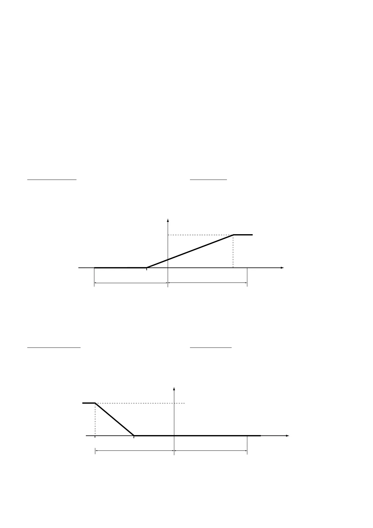
“Direct”
operation: it is wished to control, with a value of SET1=20, a
modulating actuator so as to restrain a measurement which tends to
increase (e.g. refrigeration or dehumidification).
P07 is set at P07=5 (proportional band in absolute value). Setting C22
at -20 and C23 at +80 (values as percentages of P07=5), there will be
control of the direct type, as illustrated below:
Note: the output is at minimum value for values of the controlled mea-
surement lower than 19 and at maximum value for values of the con-
trolled measurement greater than 24; between 19 and 24, values will
be intermediate. When the measurement being controlled is equal to
SET1 (20) the output will maintain an intermediate value of 20%.
“Re
verse” operation: it is wished to control, with a value of SET1=20, a
modulating actuator so as to restrain a measurement which tends to
decrease (e.g. heating or humidification). A neutral zone is required in
the region of the SET. P07 is set for a value of P07=10. Setting C22 at -
50% and C23 at -100%, there will be control of the type illustrated
below, in the “reverse” mode:
Note: The output is at min. value at values of the controlled measurement
greater than 15 and at max. value at those lower than 10; in the interval
between 10 and 15 the output will show intermediate values. Note the
neutral zone created between 15 and 20.The effective differential is equal
to 5 in relation to the 20 usable.The values considered are absolute ones.
 Loading...


