15
ENG
Gas Leakage Detector +0300047IE rel 1.1 - 26.04.2023
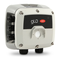
Operation
Service
wheel
LED
W2/W3 W4 W5 W6 W7 W8
Full
scale
1000
Full
scale
4000
Full
scale
10000
Full
scale
100
Voltage
[V]
[PPM] [PPM] [PPM] [PPM] [--] [m] [---] [---] [---]
6,7 670 6700 67 67
6,8 680 6800 68 68
6,9 690 6900 69 69
7 700 7000 70 70 19200 8E1
7,1 710 7100 71 71
7,2 720 7200 72 72
7,3 730 7300 73 73
7,4 740 7400 74 74
7,5 750 7500 75 75
7,6 760 7600 76 76
7,7 770 7700 77 77
7,8 780 7800 78 78
7,9 790 7900 79 79
8 800 8000 80 80 2-10 V W=0 A=1 9600 8O1
8,1 810 8100 81 81
8,2 820 8200 82 82
8,3 830 8300 83 83
8,4 840 8400 84 84
8,5 850 8500 85 85
8,6 860 8600 86 86
8,7 870 8700 87 87
8,8 880 8800 88 88
8,9 890 8900 89 89
9 900 9000 90 90 19200 8O1
9,1 910 9100 91 91
9,2 920 9200 92 92
9,3 930 9300 93 93
9,4 940 9400 94 94
9,5 950 9500 95 95
9,6 960 9600 96 96
9,7 970 9700 97 97
9,8 980 9800 98 98
9,9 990 9900 99 99
10 1000 10000 100 100 0-10 V W=1 A=1
3.4 Analogue output
The CAREL GLD series gas detectors feature a single congurable analogue output. During normal operation, the device’s ana-
logue output signal is proportional to the gas concentration measured, and can be selected from the following options:
• 1 to 5 V
• 2 to 10 V
• 0 to 10 V
• 4 to 20 mA (default)
The CAREL GLD series gas detectors use dierent voltage/current values to indicate dierent operating modes. In normal oper-
ation, the gas concentration is indicated by the analogue output signal level. The relationship between output signal level and
gas concentration is shown below:
Gas concentration 1-5 V 2-10 V 0-10 V 4-20 mA
0% 1 V 2 V 0 V 4 mA
50% 3 V 6 V 5 V 12 mA
100% 5 V 10 V 10 V 20 mA
3.5 Alarm management
The alarms are activated when the set thresholds are exceeded. The alarm threshold value must always be greater than the warning
value. The alarm and warning thresholds must be less than or equal to the full scale range, and must be greater than or equal to the
allowed limit. The alarms are activated when the set thresholds are exceeded.
Alarm set points
Sensor, gas and range Minimum value Alarm default Warning default Maximum value Unit of measure
GLD group 1 and 2 150 500 150 800 ppm
GLD group 3 400 800 400 3000 ppm
GLD group 4, CO
2
1000 5000 1500 8000 ppm
GLD group 5, NH
3
15 30 15 80 ppm
 Loading...