Electrical features
Power supply
Voltage supply range: 24 - 15%... + 10% 50/60 Hz (20.4V~26.4 Vac)
Maximum power absorbed by the device: 3W
Characteristics of the fuse (obligatory)
to be inserted in series to the unit power supply: 315mAT
Power driving
Below, as “Group A” is defined the grouping
of the following outputs: valve, pump, compressor, resistance
Max. current for each power connector: 2A
Relay output current* (each relay, resistive load): 2A 250 V~
Relay output current* (maximum 1 relay, resistive load): 3A 250 V~
Switching maximum number (each relay): 10 s (it is machine manufacturer’s duty into which the device is
integrated to ensure the proper configuration of the machine in
order to comply with this specification)
Type of relay action-microswitching: 1C
insulation between the relays of the group A: functional
ins. between the group A and the very current: reinforced
ins. between the relays of the group A
and the signalling relay: principal
ins. between the signalling relay
and the very low voltage: reinforced
insulation between the relays and the frontal: reinforced
* If higher output currents are required, please contact Carel srl.
Note: All the relays of the Group A must have the same connections as indicated on the diagram.
Digital inputs:
Electric standard: clean contact
Make current referred to ground: 4.5 mA
Make maximum resistance: 50Ω
Analog inputs:
Temperature probes are usable: Carel NTC probe (the response time depends on the component
being utilised, typical value: 90 seconds)
Pressure probe connection: through Carel converter
Analog output:
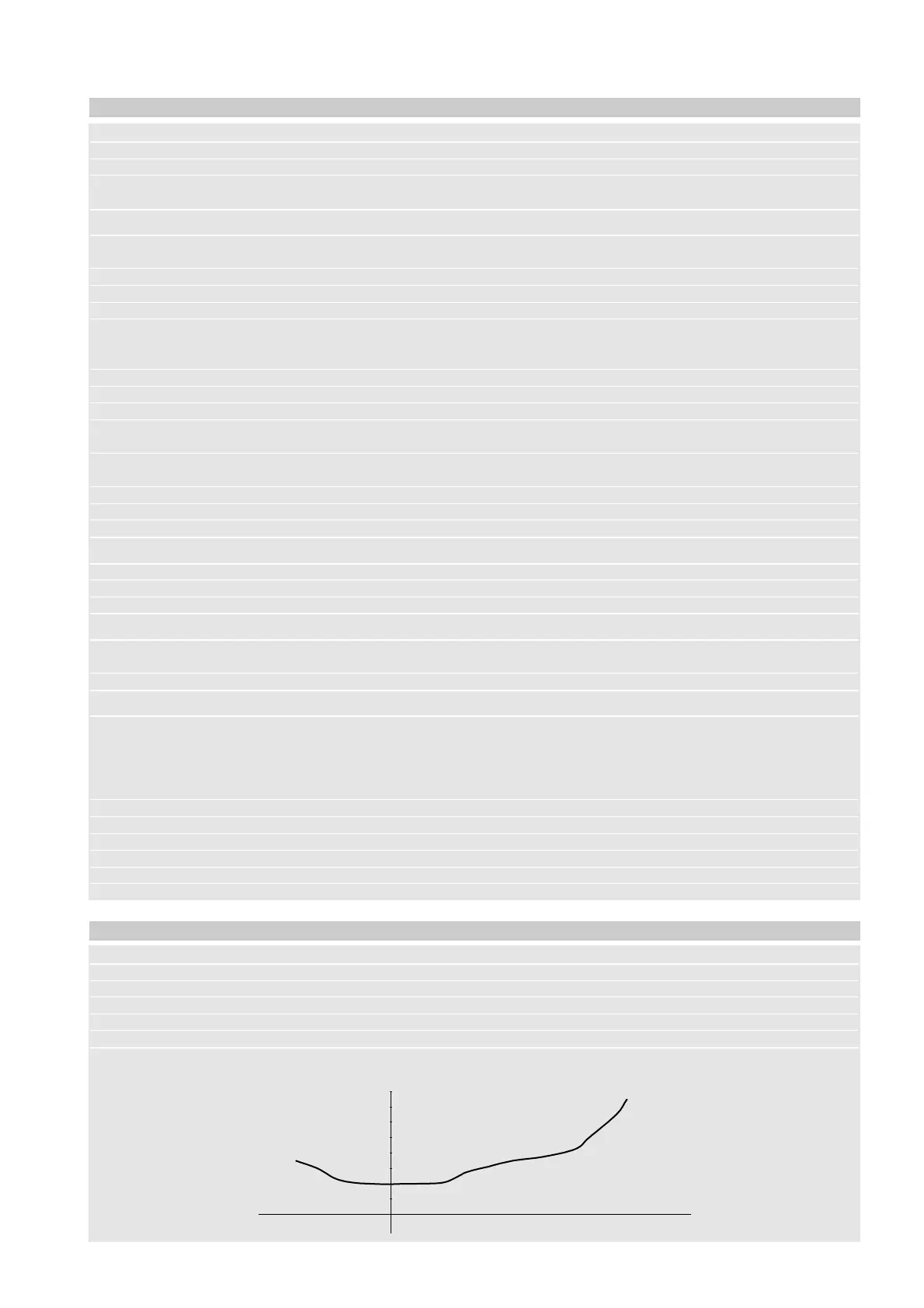
Fan output waveform: grid frequency, selectable: pulse-amplitude modulation, or pulse-
position modulation, with selectable amplitude.
The output is intended for the connection of the MCHRTF***0,
CONVONOFF0 and CONV0/10A0 Carel driving-modules, for the
control of variable and fixed speed fans.
Fan output open-circuit (referred to ground): 4.8V±10%
Fan output ground short-circuit current: 30mA
Minimum output load: 1kΩ
Electrical stress across isulating parts: long period
Immunity of the device against overvoltage: category 1
The output waveform selection is obtained thorough parameters as described in the user manual of the device.
Functional features
Precision:
Resolution in the -20°C~+20°C measurement range: 0.1°C
Res. in the -40°C~ -20 °C and +20°C~ +80 °C measur. range: 1°C
Temp. measur. errors in the -20°C~ +20 °C measur. range: ±0.5 °C (probe excluded)
Temp. measur. errors in the -40 °C~ +80 °C measur. range: ±1.5 °C (probe excluded)
Pressure measurement errors, input 0.64~3.2 V: 2% (probe and converter excluded)
10. µchiller compact technical specifications