21
ENG
mpxone +0300086EN rel. 2.2 - 13.11.2023
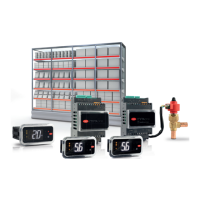
Installation
DIN (Advanced)
Secondary 1
Main
Secondary 2
Remote display
ExV
User terminal
J8J14
J5 J4
J8J14
J5
300086_050_R01
J8
J5
up to 9 secondary for
Medium and
Advanced models,
up to 5 secondary only
for Basic model
advanced
J14
Fig. 2.w
RS485 supervisor network
Notice: on the main controller, parameter H3 must be set based on the protocol used by the supervisory system (Modbus/
Carel). On the secondary devices, parameter H3 should always be left at the default value (1=Modbus).
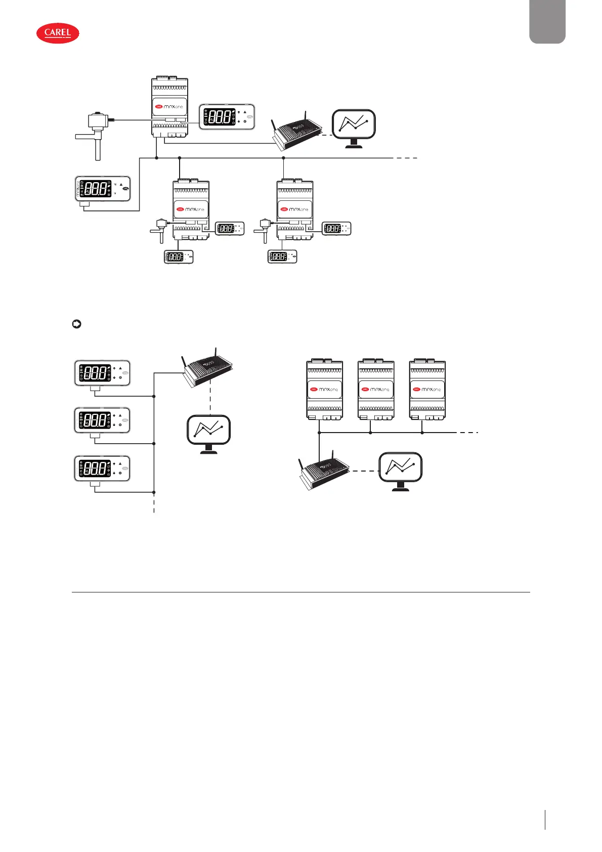
Main 1
Main 2
Main 3
300086_019_R01
J4
J4
J4
Main 1 Main 2 Main 3
300086_023_R01
J4 J4 J4
Fig. 2.x Fig. 2.y
2.11 Installation
For installation proceed as follows, with reference to the wiring diagrams:
• before performing any operations on the control board, disconnect the main power supply by turning the main switch in the
electrical panel OFF;
• avoid touching the control board, as electrostatic discharges may damage the electronic components;
• the index of protection required for the application must be ensured by the manufacturer of the cabinet or by suitable as-
sembly of the controller;
• connect any digital inputs, Lmax = 10 m;
• connect the actuators: the actuators should only be connected after having programmed the controller. Carefully evaluate
the maximum ratings of the relay outputs as indicated in “Controller electrical and physical specifi cations”;
• program the controller: see “User interface”;
• for the connection of the main/secondary network and user interfaces, use shielded cable and check the maximum distances
and cable sizes specifi ed in “Electrical specifi cations”;
• for safety devices (e.g. circuit breakers), comply with the following requirements:
– IEC 60364-4-41;
– standards in force in the country;
– connection technical requirements of the power company.