Standard air-conditioning units
Carel Cod. +030221421 – Rel. 1.2 – April, 11, 2003
33
14.0 TEMPERATURE SET POINT COMPENSATION
The temperature set point can be “compensated” automatically for comfort reasons; for example, think about a commercial concern in which
people frequently enter and go out: if internal temperature is 10°C lower than the external one, the thermal rush may annoy people and could be
prejudicial to their health. The maximum difference between internal and external temperatures should not exceed 6°C in order to obtain
optimum comfort. In this case, the compensation function increases the set point by 4°C, consequently increasing the ambient temperature; this
function prevents the difference between internal and external temperature from exceeding 6°C.
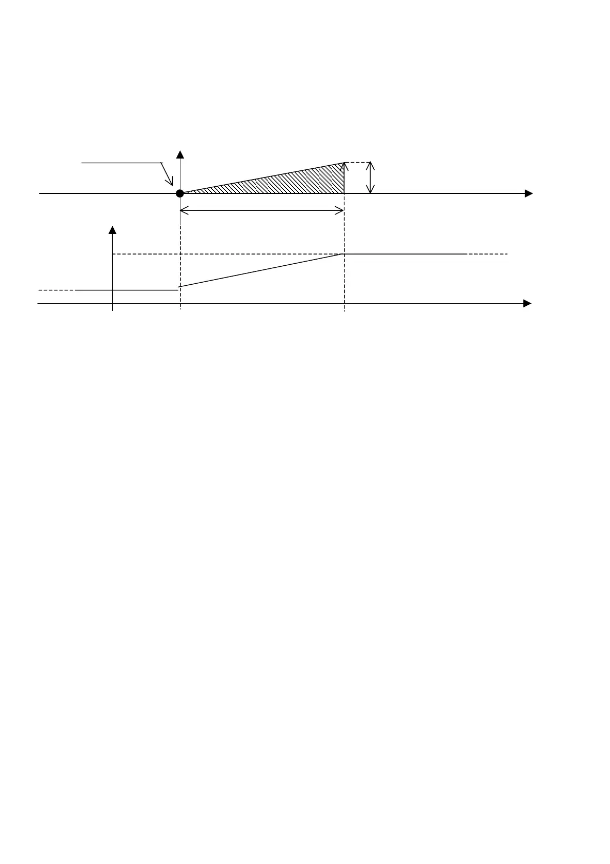
Compensation requires a temperature probe to be installed at the exterior. The function is managed based on the values of compensation set
point, differential and offset parameters, as shown in the following diagram:
15.0 COMPRESSORS
Compressors are managed in ON-OFF mode. Maximum 2 compressors can be present, each having capacity control. Therefore, the total amount
of compressors + capacity controls allows for 4 cold steps.
15.1 CAPACITY CONTROL
Their logic can be N.O. (relays normally open) or N.C. (relays normally closed). With respect to compressors, these controls are enabled with a
programmable delay time. The capacity controls are available for medium boards only. During dehumidification, capacity controls are started
simultaneously with the compressors to obtain the maximum cooling power.
15.2 ROTATION
Compressors rotation follows the F.I.F.O. (first in, first out) logic. The first compressor turned on is the first to turn off, the first compressor
turned off is the last to turn on. This logic allows comparing the compressors working hours and obtaining the same ageing.
15.3 TIMING
15.3.1 START MINIMUM TIME
It represents the compressors start minimum time (in seconds) after they have been enabled. If a stop request arises, compressors are disabled
only after the established time has elapsed.
15.3.2 STOP MINIMUM TIME
It represents the compressors stop minimum time (in seconds) after they have been disabled. If a start request arises, compressors are enabled
only after the established time has elapsed.
15.3.3 MINIMUM TIME BETWEEN DIFFERENT COMPRESSORS STARTS
It represents the minimum time interval (in seconds) between start of a device and the following one. This interval allows preventing
contemporary peaks, which would cause a high energy absorption.
15.3.4 MINIMUM TIME BETWEEN COMPRESSOR STARTS
It represents the minimum time interval (in seconds) between two starts of the same device. This parameter allows limiting the number of starts
per hour. If, for example, the maximum number of starts per hour allowed by the default values is 10, this limit can be respected by setting a
360-second time interval.
15.3.5 CAPACITY CONTROLS START MINIMUM TIME
It represents the minimum time between compressor and capacity control start. This parameter is available only if capacity controls have been
selected.
External
tem
.
°C
Compensation
offset
Compensation proportional band
Compensation set
25.0 28.0
3°C
Temperature set-
oint
°C
23.0°C
2°C
25.0°C
 Loading...


