Standard air-conditioning units
Carel Cod. +030221421 – Rel. 1.2 – April, 11, 2003
14
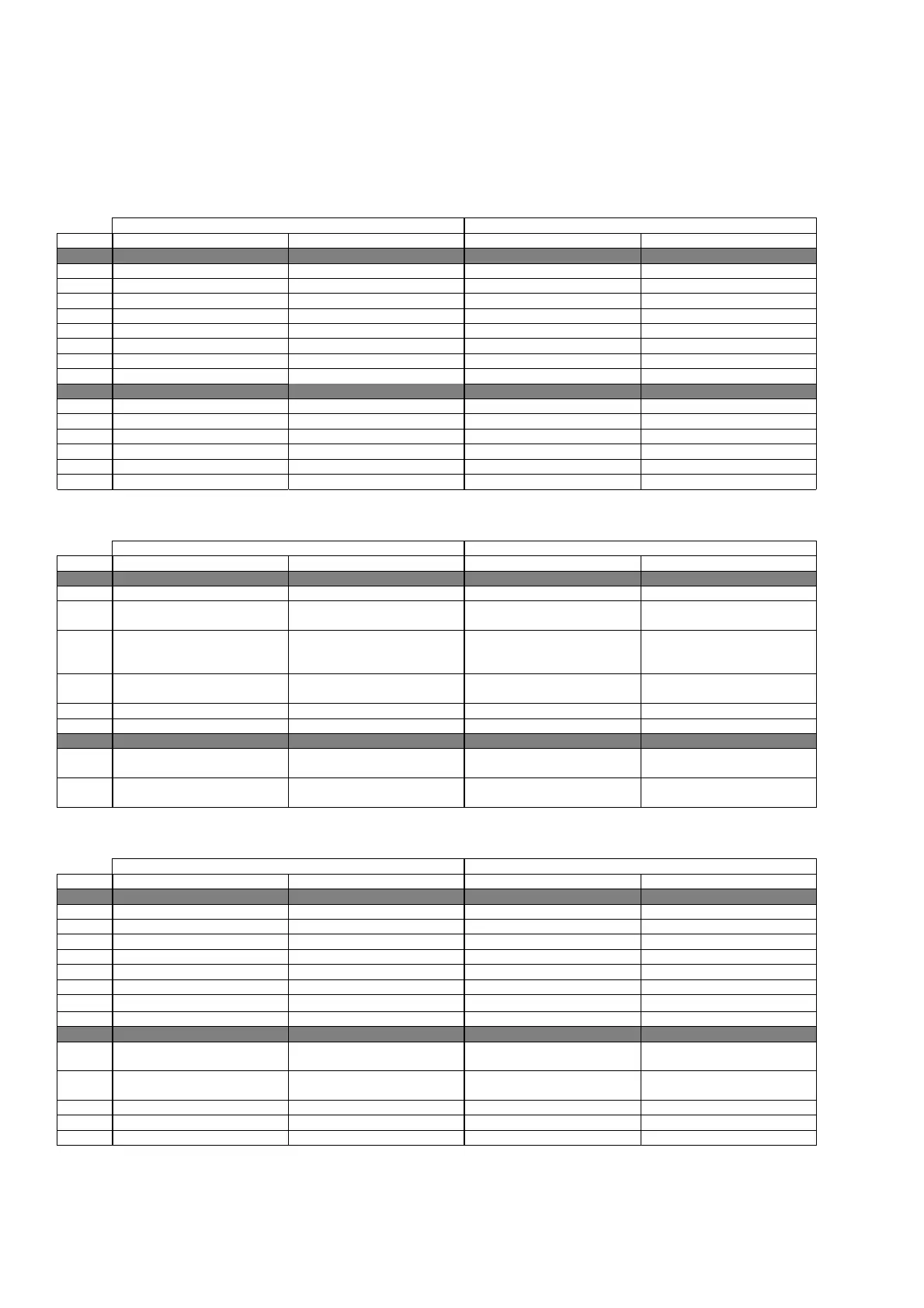
5.0 CONFIGURATION LIST
The pCO1/pCO2 small/medium boards allow managing both “ED” direct expansion and “CW” water coil air-conditioning units. When started,
the program recognises the board type and size, consequently prearranging inputs and outputs, also based on the air-conditioning unit type (ED
or CW) established in the Manufacturer branch. The following tables indicate inputs and outputs configurations in the possible combinations.
The multiple items (xxx / xxx / …) indicate different inputs and outputs purposes; selection is carried out by Manufacturer screens branch
parameters. As for wiring harness, refer to the technical manual of the pCO1 and pCO2 boards.
5.1 DIGITAL INPUTS
ED CW
N. pCO1 – pCO2 SMALL pCO1 – pCO2 MEDIUM pCO1 – pCO2 SMALL pCO1 – pCO2 MEDIUM
ID 1 C1 alarm / C1 low pressure C1 alarm Flooding / fire alarm Flooding alarm
ID 2 C2 alarm / C1 high pressure C2 alarm Summer – Winter selection Summer – Winter selection
ID 3 Heater 1 thermal alarm Heater 1 thermal alarm Heater 1 thermal alarm Heater 1 thermal alarm
ID 4 Heater 2 thermal alarm Heater 2 thermal alarm Heater 2 thermal alarm Heater 2 thermal alarm
ID 5 Fire / filter / flooding alarm Dirty filters alarm Dirty filters alarm Dirty filters alarm
ID 6 Fan thermal alarm Fan thermal alarm Fan thermal alarm Fan thermal alarm
ID 7 Air flow controller alarm Air flow controller alarm Air flow controller alarm Air flow controller alarm
ID 8 Remote On-Off Remote On-Off Remote On-Off Remote On-Off
ID 9 --- C1 low pressure alarm --- Auxiliary alarm
ID 10 --- C2 low pressure alarm --- Water flow controller alarm
ID 11 --- Humidifier water level --- Humidifier water level
ID 12 --- Fire / flooding alarm --- Fire alarm
ID 13 --- C1 cond. fan thermal alarm --- ---
ID 14 --- C2 cond. fan thermal alarm --- ---
5.2 ANALOGUE INPUTS
ED CW
N. pCO1 – pCO2 SMALL pCO1 – pCO2 MEDIUM pCO1 – pCO2 SMALL pCO1 – pCO2 MEDIUM
B 1 Ambient humidity Ambient humidity Ambient humidity Ambient humidity
B 2 C1 high press. / C1 cond. temp. /
Outlet temperature (pCO2)
C1 high press. /
C1 cond. temp.
Outlet temperature Outlet temperature
B 3 C2 high press. /
C2 cond. temp. /
Recovery temperature
C2 high press. / C2 cond. temp. /
Recovery temperature (pCO2) /
Humidif. conductibility (pCO1)
Recovery temperature Recovery temperature (pCO2) /
Humidif. conductibility (pCO1)
B 4 External temperature External temperature (pCO2)
Humidifier current (pCO1)
External temperature External temperature (pCO2) /
Humidifier current (pCO1)
B 5 Ambient temperature Ambient temperature Ambient temperature Ambient temperature
B 6 Outlet temperature (pCO1)
Outlet temperature FREE FREE
B 7 --- Humidif. conductibility
(pCO2)
Recovery temperature (pCO1)
--- Humidif. conductibility (pCO2)
B 8 --- Humidifier current (pCO2)
External air temperature (pCO1)
--- Humidifier current (pCO2)
5.4 DIGITAL OUTPUTS
ED CW
N. pCO1 – pCO2 SMALL pCO1 – pCO2 MEDIUM pCO1 – pCO2 SMALL pCO1 – pCO2 MEDIUM
DO 1 Outlet fan Outlet fan Outlet fan Outlet fan
DO 2 Compressor 1 Compressor 1 Cold valve opening / single Cold valve opening / single
DO 3 Compressor 2 Compressor 2 Cold valve closing / single Cold valve closing / single
DO 4 Resist.1 / Warm valve opening Resist.1 / Warm valve opening Resist.1 / Warm valve opening Resist.1 / Warm valve opening
DO 5 Resist.2 / Warm valve closing Resist.2 / Warm valve closing Resist.2 / Warm valve closing Resist.2 / Warm valve closing
DO 6 Dehumidification Dehumidification Dehumidification Dehumidification
DO 7 Recovery
Recovery / N
on-serious alarms
Recovery
Recovery / Non-serious alarms
DO 8 Generic alarms Serious alarms Generic alarms Serious alarms
DO 9 --- C1 cond. fan / C1 capacity
control
--- ---
DO 10 --- C2 cond. fan / C2 capacity
control
--- ---
DO 11 --- Humidification --- Humidification
DO 12 --- Humidifier water load --- Humidifier water load
DO 13 --- Humidifier water drain --- Humidifier water drain
 Loading...


