Standard air-conditioning units
Carel Cod. +030221421 – Rel. 1.2 – April, 11, 2003
3
1.0 GENERAL INFORMATION
1.1 THE PROGRAM
The “standard air-conditioning units” program can be used with CAREL’s pCO1 or pCO2 boards; the program manages “ED” direct expansion
or “CW” water coil air-conditioning units.
The program main functions are:
• control of temperature and humidity inside civil or technological environments
• management of 1 to 2 hermetic or semi-hermetic compressors
• management of 1 to 3 heaters
• 0-10Volt and three-position modulating heating valves
• 0-10Volt and three-position modulating cooling valves
• Carel’s external or built-in humidifier with immersed electrodes
• on-off or modulated condensing fans, pressure- or temperature-controlled
• outlet temperature control
• alarms management, alarm data logging, devices timing, warnings
• complete management of devices timing
• connection with local and BMS supervisory networks (LonWorks, Bacnet, Modbus…)
The LCD terminal displays the following data, modifiable at any time:
• measurement of connected probes and calibration, if required
• unit start and stop
• alarms detection
• programming of configuration and operative parameters with access protected by password
• controlled devices working hours and time bands with access protected by password
• programming of clock and time bands with access protected by password
• language selection among the available options (English, Italian, German, French, Spanish)
The connection with CAREL’s pLAN network allows the program to manage the following functions as well:
• automatic time or event rotation among up to 8 units
• control of temperature and humidity of max. 8 units, taking the probes of unit no. 1 as a reference
• use of only one LCD terminal for controlling up to 8 units
WARNING: to avoid tampering during device operation, the qualified personnel only shall know the passwords.
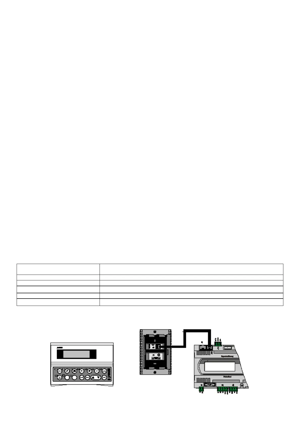
1.2 THE USER TERMINAL
The provided terminal is equipped with LCD display (4 rows x 20 columns) and can be of two types: “built-in” terminal, with 6 buttons only, or
external terminal (connected by telephone cable) with 15 buttons. Both terminals allow carrying out all program operations. The user terminal
allows displaying the unit working conditions at any time and modifying the parameters; furthermore, it may also be disconnected from the
main board, as its presence is not strictly necessary.
1.2.1 BUTTON LEDS
The EXTERNAL terminal is provided with three LEDS under the rubber buttons; the BUILT-IN terminal is provided with four LEDS. They
indicate respectively:
ON/OFF button (ext. terminal) green LED – indicates that the unit is ON; the LED blinks if OFF from supervisor, remote digital
input and time bands
ENTER button (ext. terminal) yellow LED – indicates that the device is correctly powered
ALARM button (shared term.) red LED – indicates the presence of alarms
ENTER button (built-in term.)
yellow LED – see the ON/OFF button (external terminal)
PROG button (built-in term.) green LED – indicates that a screen branch other than the Menu branch is being accessed
ESC button (built-in term.)
green LED – indicates that the Menu branch is being accessed
1.2.2 EXTERNAL TERMINAL
 Loading...


