Standard Chiller/HP modulare per compressore a vite con driver CAREL
Cod.: +030221241 Rel. 1.0 dated 25 September 03
26
11.2 Stepped capacity control with control at inlet
A description of stepped capacity control of 4 compressors with four capacity control steps each:
Control set point
Evaporator inlet temperature
Control band
C4P1
P2 P3 P4
C1P1
P2 P3 P4
C2P1
P2 P3 P4
C3P1
P2 P3 P4
All compressors and the relevant capacity control steps will be proportionally positioned in the band. Increasing temperature values will cause
the control steps to be subsequently input. Each step will be input according to the set delay times.
The compressors will be started at the first entered capacity control stage. If special management of the first capacity control stage was selected,
control will be effected according to the description in the dedicated section.
In any event, the times for the capacity controls will be applied as described.
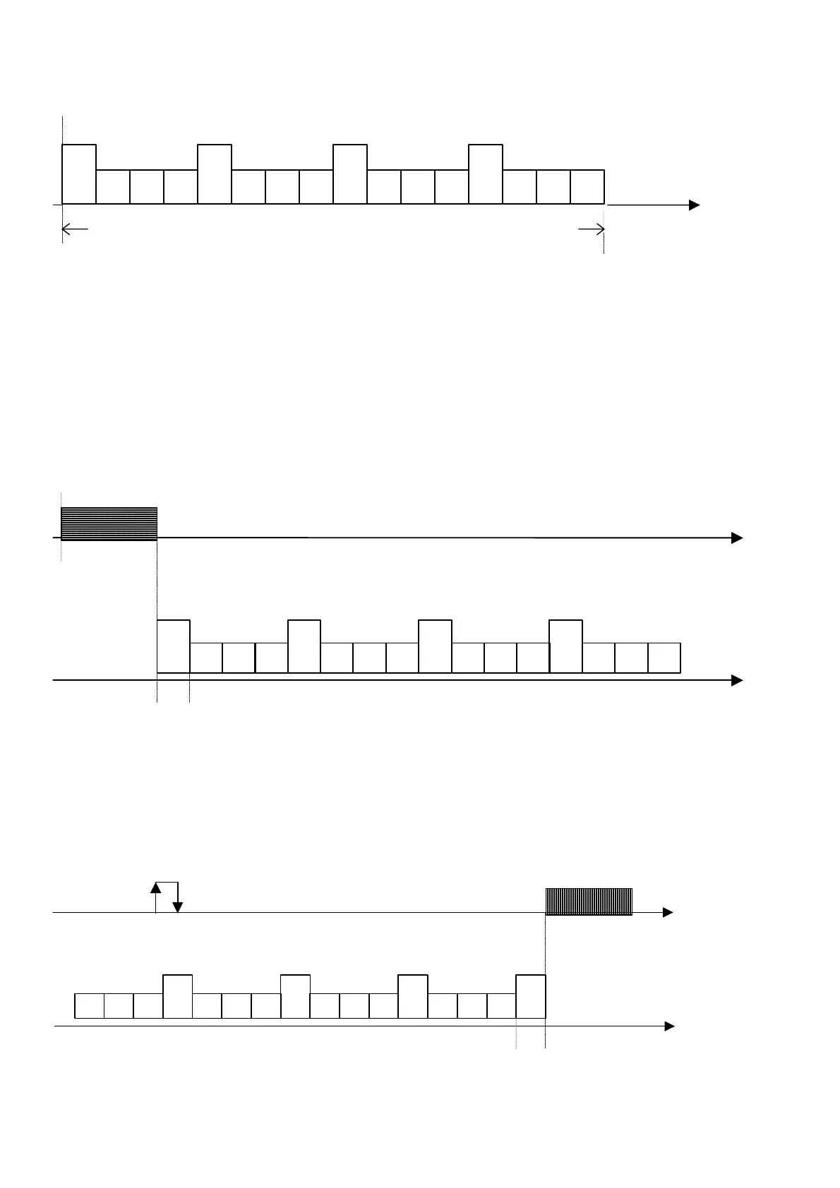
11.3 Stepped capacity control with control at outlet
A description of stepped capacity control of 4 compressors with four capacity control steps each:
11.3.1 Activation of compressors
if the water temperature measured by the probe located at the evaporator outlet exceeds the threshold of Control Set-point + Control Band (Point
B), the number of power stages will be increased - the power stages were input according to the set parameter known as "delay between power-
up of different devices".
Evaporator Outlet Temperature
Point B
Control set point
C4P1
P2 P3 P4
C1P1
P2 P3 P4
C2P1
P2 P3 P4
C3P1
P2 P3 P4
Time [s]
Devices activation delay
The activation delay of the different devices is the same, without distinction of compressors and capacity control steps.
The activation delay times for the capacity controls are considered only if the step activation delay is shorter than the set delays. In this way, the
power increase speed of the compressor is reduced. If the difference between the times is too high, if there is a powered up, but not fully loaded
compressor, the next compressor could be started.
11.3.2 Power-down of compressors
If the water temperature measured by the probe located at the evaporator outlet is below the Control Set-point (Point A), the number of power stages
will be reduced - power stages were input according to the set parameter known as "delay between power-downs of different devices".
Delayed disablement of devices
Forced power-down
threshold
Evaporator outlet temperature
Point A
control set
point
C4P1
P2
P3
P4
C1P1
P2P3P4
C2P1
P2P3P4
C3P1
P2
P3
P4
Time [s]
If temperature falls below the set forced power-down threshold, the compressors are powered down irrespective of the set delays, in order to
prevent tripping the antifreeze alarm.

 Loading...


