Standard Chiller/HP modulare per compressore a vite con driver CAREL
Cod.: +030221241 Rel. 1.0 dated 25 September 03
14
7 LIST OF PARAMETERS
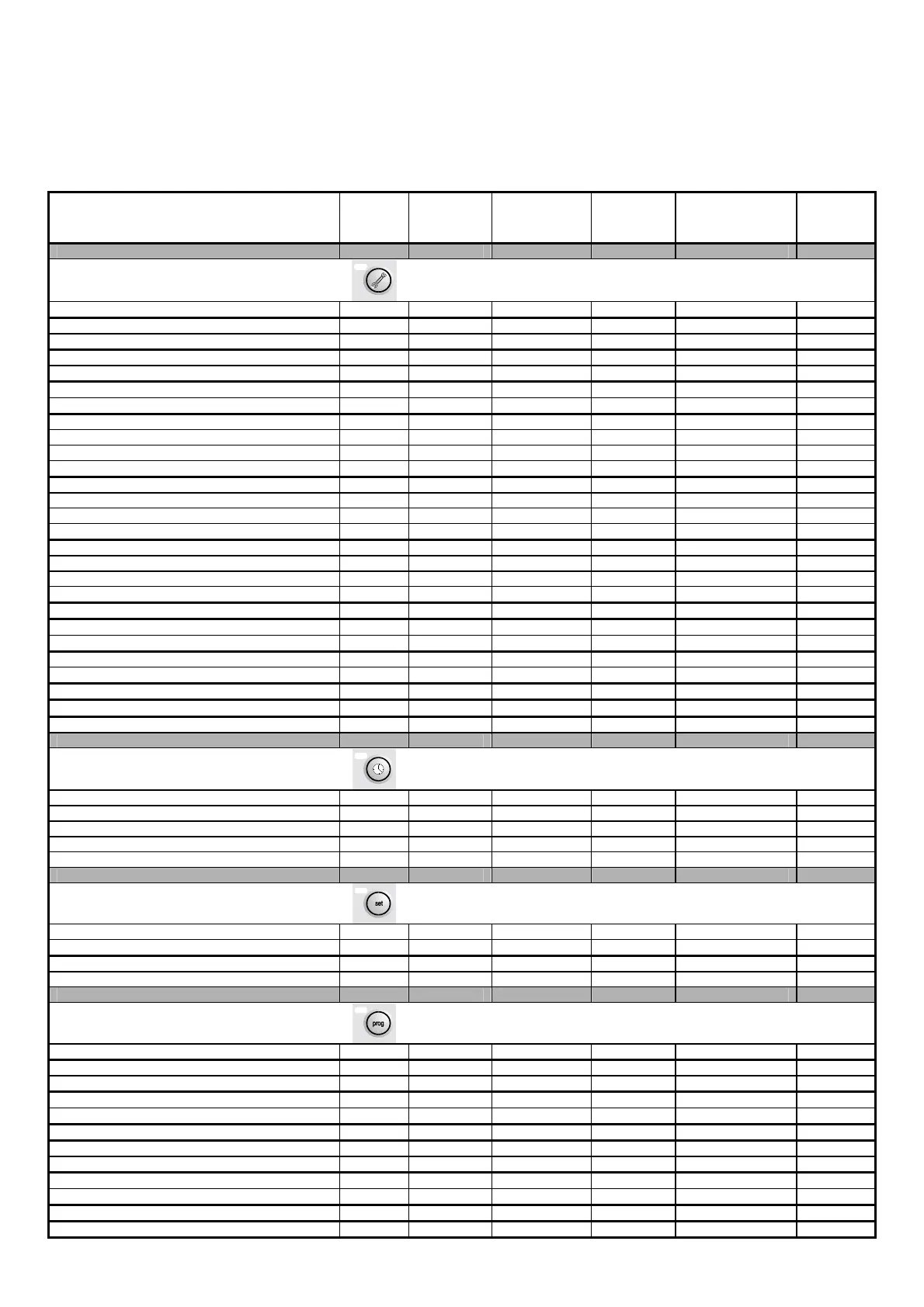
The table below describes program parameters along with the following additional information: screen code (screens have a code in the top right
corner) to make identifying the parameter easier (screen), factory setting, upper and lower limits of the range within which values can be
effected, unit of measurement, and an empty column for writing the desired value.
To find the parameter you are interested in on the terminal’s display, proceed as follows:
• Locate the parameter in the table below and the code of the screen it appears on
• Using the list of screens (coming section) and screen code, call up the screen on the terminal
DESCRIPTION OF PARAMETER SCREEN MASTER
SLAVE
FACTORY
VALUE
USER
VALUE
RANGE MEASU-
REMENT
UNIT
Password inputting A3 M/S 1234 0 to 9999
Duty hours thresholds for evaporator pump A4 M 10 0 to 999 hours x 1000
Reset duty hours thresholds for evaporator pump A4 M N. N/Y
Duty hours thresholds for condenser pump A5 M 10 0 to 999 hours x 1000
Reset duty hours thresholds for condenser pump A5 M N. N/Y
Duty hours thresholds for compressor A6 M 10 0 to 999 hours x 1000
Reset compressor duty hours A6 M N. N/Y
Adjustment of probe B1 A7 M/S 0 -9.9 to 9.9
Adjustment of probe B2 A7 M/S 0 -9.9 to 9.9
Adjustment of probe B3 A7 M/S 0 -9.9 to 9.9
Adjustment of probe B4 A7 M/S 0 -9.9 to 9.9
Adjustment of probe B5 A8 M/S 0 -9.9 to 9.9
Adjustment of probe B6 A8 M/S 0 -9.9 to 9.9
Adjustment of probe B7 A8 M/S 0 -9.9 to 9.9
Adjustment of probe B8 A8 M/S 0 -9.9 to 9.9
Enable compressor 1 A9 M S N/Y
Enable compressor 2 A9 M S N/Y
Enable compressor 3 A9 M S N/Y
Enable compressor 4 A9 M S N/Y
Cancel alarm log Aa M/S N. N/Y
Adjustment mode for Driver 1 valve Ab M/S Automatic Aut-Man
Number of steps for manual opening of Driver 1 valve Ab M/S 0 0 to 9999 Steps
Adjustment mode for Driver 2 valve Ac M/S Automatic Aut-Man
Number of steps for manual opening of Driver 2 valve Ac M/S 0 0 to 9999 Steps
Manual release of Driver 1 at start-up Ad M/S No No-Yes
Manual release of Driver 2 at start-up Ae M/S No No-Yes
Inputting of new Maintenance password Af M/S 1234 0 to 9999
Hour setting K1 M/S current hour 0 to 23 Hours
Minute setting K1 M/S current minutes 0 to 59 minutes
Day setting K1 M/S current day 1 to 31
Month setting K1 M/S current month 1 to 12
Year setting K1 M/S current year 0 to 99
Summer set point S1 M/S 12.0 see P1 °C
Winter set point S1 M 45.0 see P2 °C
Second summer set-point S2 M 45.0 see P1 °C
Second winter set point S2 M/S 45.0 see P2 °C
M/S
User password inputting P0 M/S 1234 0 to 9999
Minimum limit of summer set point P1 M/S 7.0 -99.9 / 99.9 °C
Minimum limit of summer set point P1 M 17.0 -99.9 / 99.9 °C
Minimum limit of winter set point P2 M 40.0 -99.9 / 99.9 °C
Minimum limit of winter set point P2 M 50.0 -99.9 / 99.9 °C
Selection of control probe P3 M Input Input / Output
Control with probe at evaporator input P4 M Prop. Prop./Prop+Int.
Integration time P4 M 600 0 to 9999 seconds
Control at output - summer forced power down P5 M 5.0 -99.9 / 99.9 °C
Control at output - winter forced power down P5 M 47.0 -99.9 / 99.9 °C
Control band P6 M 3.0 0 to 99.9 °C
Neutral zone with modulating capacity control P7 M/S 1.0 0 to 99.9 °C

 Loading...


