Standard Chiller/HP modulare per compressore a vite con driver CAREL
Cod.: +030221241 Rel. 1.0 dated 25 September 03
15
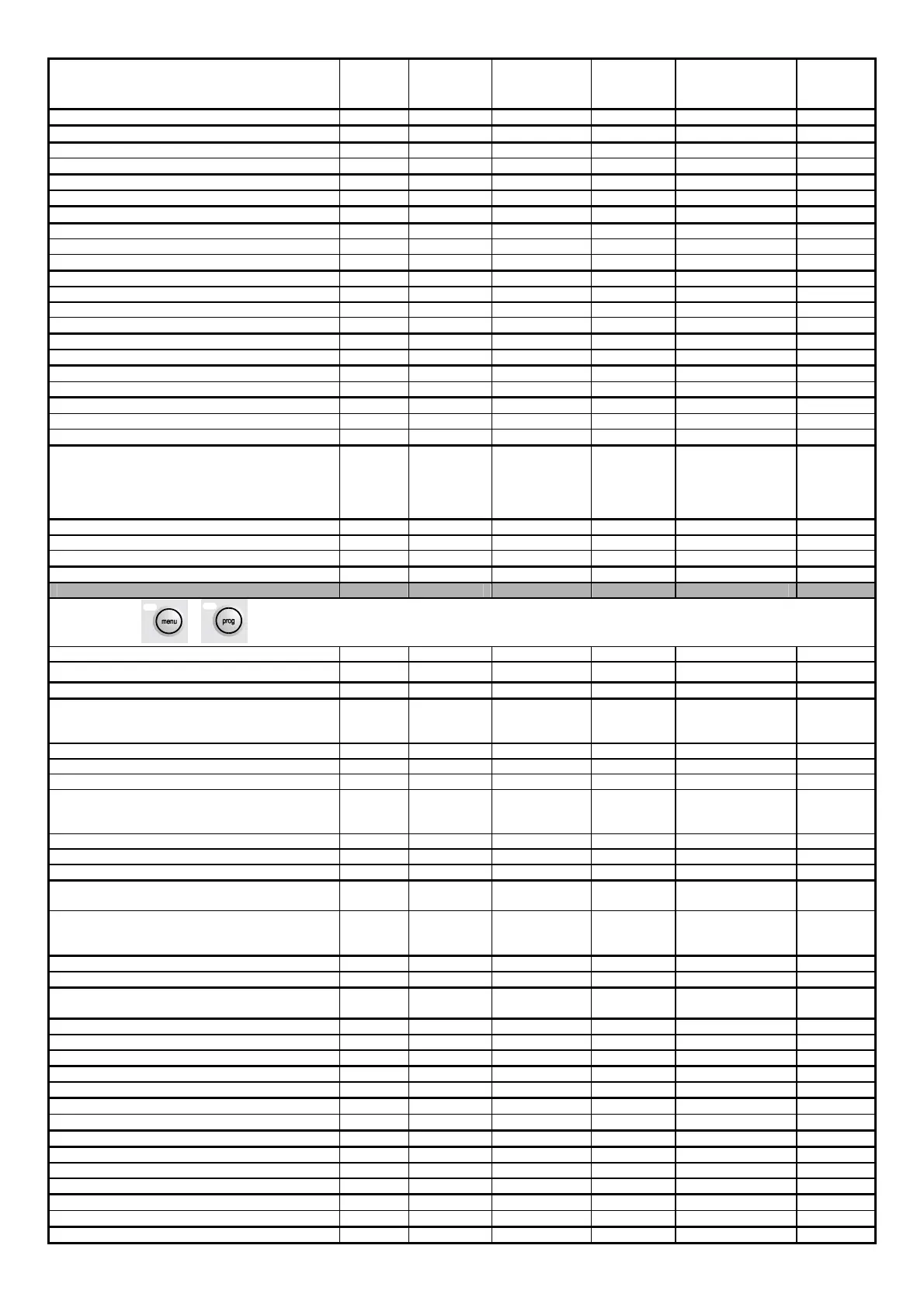
DESCRIPTION OF PARAMETER SCREEN MASTER
SLAVE
FACTORY
VALUE
USER
VALUE
RANGE MEASU-
REMENT
UNIT
Delayed power up between pump and compressors P8 M 5 0 to 999 seconds
Delayed power down of main pump P9 M 5 0 to 999 seconds
Enable remote On/Off Pa M/S N. N/Y
Enable On/Off from supervisor Pa M/S N. N/Y
Enable summer / winter selection from digital input Pb M N. N/Y
Enable summer / winter selection from supervisor Pb M N. N/Y
Enable language mask start-up Pc M/S S N/Y
Type of freecooling control Pd M/S Prop. Prop./Prop+Int.
Integral time for freecooling management Pd M/S 150 0 to 9999 seconds
Freecooling offset on set-point Pd M/S 5.0 0 to 99.9 °C
Minimum freecooling delta Pe M/S 2.0 0 to 99.9 °C
Maximum freecooling delta Pe M/S 10.0 0 to 99.9 °C
Freecooling differential Pe M/S 4.0 2.0 to 99.9 °C
Compressors delay in freecooling Pe M/S 5 0 to 500 minutes
Minimum threshold for freecooling valve start Pf M/S 50 0 to 100 %
Maximum threshold for freecooling valve opening Pf M/S 50 0 to 100 %
Defrosting starts Pg M/S 2.0 -99.9 / 99.9 °C/bar
Defrosting ends Pg M/S 12.0 -99.9 / 99.9 °C/bar
Drip-off time Ph M/S 10 5 to 999 seconds
Delayed defrosting start Ph M/S 1800 0 to 32000 seconds
Maximum defrosting time Ph M/S 300 0 to 32000 seconds
Cycle reversing configuration Pi M/S Comp. always
on
Comp. always ON
Comp. OFF start of
defr. Cmp. OFF end
defr. Comp. OFF
start/end
Card identification number for supervision network Pj M/S 1 0 to 200
Card communication speed for supervision network Pj M/S 19200 1200 to 19200 bps
Selection of communication serial network Pj M/S Carel Carel / Modbus
New user password inputting Pk M/S 1234 0 to 9999
+
Constructor password inputting Z0 M/S 1234 0 to 9999
CONFIGURATION →
Unit configuration C1 M/S 0 0 to 5
Enable probe B1 C2 M/S Y (if pCO2)
N (if pCO1)
Y (if pCOC)
N/Y
Enable probe B2 C2 M/S N. N/Y
Enable probe B3 C2 M/S N. N/Y
Enable probe B4 C2 M/S N. N/Y
Enable probe B5 C2 M/S N (if pCO2)
Y (if pCO1)
N (if pCOC)
N/Y
Enable probe B6 C2 M/S N. N/Y
Enable probe B7 C2 M/S N. N/Y
Enable probe B8 C2 M/S N. N/Y
Generic probe generic configuration (B4 on pCO1, B5
on pCOC, B6 on pCO2)
C3 M/S None No Current Voltage
external Set-point
Type of generic probe C3 M/S 0 - 1 V 0-1 V
0-10 V
4-20mA
Generic probe lower limit C4 M/S 0.0 -999.9 to 999.9 °C/V/A
Generic probe upper limit C4 M/S 0.0 -999.9 to 999.9 °C/V/A
Probe types for analogue inputs 1 and 2 (for pCO1
cards only)
C5 M/S 4-20mA 4-20mA / 0-5V
Type of delivery temperature probe C6 M/S Ntc Ntc / 4-20mA
Delivery probe lower limit C6 M/S -30.0 -999.9 to 999.9 °C
Delivery probe upper limit C6 M/S 150.0 0.0 to 999.9 °C
High pressure probe lower limit C7 M/S 00.0 -99.9 to 99.9 bar
High pressure probe upper limit C7 M/S 30.0 -99.9 to 99.9 bar
Low pressure probe lower limit C8 M/S -0.5 -99.9 to 99.9 bar
Low pressure probe upper limit C8 M/S 7.0 -99.9 to 99.9 bar
Enable double set-point C9 M Disabled Disabled / Enabled
Number of drivers present Ca M/S 0 0 to 2
Number of compressors present Ca M/S 1 1 to 4
Compressor rotation Ca M S N/Y
Type of capacity control Cb M/S Steps Step/Modul.
Number of steps per compressor Cb M/S 4 1 to 4
Enable starting restrictions Cc M/S N. N/Y

 Loading...


