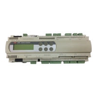
Standard Chiller/HP modulare per compressore a vite con driver CAREL
Cod.: +030221241 Rel. 1.0 dated 25 September 03
16
DESCRIPTION OF PARAMETER SCREEN MASTER
SLAVE
FACTORY
VALUE
USER
VALUE
RANGE MEASU-
REMENT
UNIT
Step 1 - Relay 1 logic Cd M/S ON OFF/ON
Step 1 - Relay 2 logic Cd M/S OFF OFF/ON
Step 1 - Relay 3 logic Cd M/S OFF OFF/ON
Step 2 - Relay 1 logic Ce M/S OFF OFF/ON
Step 2 - Relay 2 logic Ce M/S OFF OFF/ON
Step 2 - Relay 3 logic Ce M/S ON OFF/ON
Step 3 - Relay 1 logic Cf M/S OFF OFF/ON
Step 3 - Relay 2 logic Cf M/S ON OFF/ON
Step 3 - Relay 3 logic Cf M/S OFF OFF/ON
Step 4 - Relay 1 logic Cg M/S OFF OFF/ON
Step 4 - Relay 2 logic Cg M/S OFF OFF/ON
Step 4 - Relay 3 logic Cg M/S OFF OFF/ON
Enable step 1 special management Ch M/S N. N/Y
Stand-by configuration for relay 6 Ci M/S OFF OFF/ON
Stand-by configuration for relay 7 Ci M/S ON OFF/ON
Reducing configuration for relay 6 Cj M/S ON OFF/ON
Decrementing configuration for relay 7 Cj M/S ON OFF/ON
Incrementing configuration for relay 6 Ck M/S OFF OFF/ON
Incrementing configuration for relay 7 Ck M/S OFF OFF/ON
Pulse period for modulating configuration Cl M/S 6 0 to 99 seconds
Minimum decrementing pulse Cl M/S 1.5 0 to 99.9 seconds
Maximum decrementing pulse Cl M/S 3.0 0 to 99.9 seconds
Derivation time for modulating configuration Cm M/S 3 seconds
Minimum decrementing pulse Cm M/S 1.5 0 to 99.9 seconds
Maximum decrementing pulse Cm M/S 3.0 0 to 99.9 seconds
Decrement forcing time at compressor start Cn M/S 20 0 to 999 seconds
Enable solenoid forcing when compressor OFF Co M/S N. N/Y
Enable pump - down Cp M/S N. N/Y
Minimum pump - down time Cp M/S 50 0 to 999 seconds
Configuration of compressor power level in case of
forced capacity control.
Cq M/S Max. power Max. power / Min.
power
Enable condensation Cr M/S No NO/YES
Type of condensation control Cr M/S Inverter Inverter / Steps
Number of fans per condenser Cr M/S 1 1 to 2
Enable clock card Cs M/S Disabled Disabled / Enabled
PARAMETERS →
Starting restrictions - low pressure G0 M/S
Starting restrictions - high pressure G0 M/S
Starting restrictions - pressure equalisation G0 M/S
Enable high pressure prevention G1 M/S N. N/Y
Type of high condensation prevention G1 M/S Pressure Press / Temp
Condensation set-point G1 M/S 20.0 0 to 99.9 bar/ °C
High condensation differential G1 M/S 2.0 0 to 99.9 bar/ °C
Enable delivery prevention G2 M/S N. N/Y
Delivery prevention set-point G2 M/S 90.0 0 to 999.9 °C
Delivery prevention differential G2 M/S 5.0 0 to 99.9 °C
Antifreeze prevention set point G3 M/S 6.0 -99.9 to 99.9 °C
Antifreeze prevention differential G3 M/S 1.0 0 to 99.9 °C
Condensation set-point G4 M/S 14.0 -999.9 to 999.9 bar/ °C
Condensation differential G4 M/S 2.0 -999.9 to 999.9 bar/ °C
Inverter maximum speed G5 M/S 10.0 0.0 to 10.0 V
Inverter maximum speed G5 M/S 3.0 0.0 to 10.0 V
Maximum speed time G5 M/S 10 0 to 99 seconds
Enable serious alarm G6 M/S N. N/Y
Enable phase monitor alarm G6 M/S N. N/Y
Enable evaporator flow-switch alarm G7 M/S N. N/Y
Enable condenser flow-switch alarm G7 M/S N. N/Y
Alarm set-point for delivery temperature probe G8 M/S 120.0 0 to 999.9 °C
Alarm differential for delivery temperature probe G8 M/S 5.0 0 to 99.9 °C
High pressure probe alarm set-point G9 M/S 21.0 0 to 99.9 bar
High pressure probe alarm differential G9 M/S 2.0 0 to 99.9 bar
Low pressure probe alarm set-point Ga M/S 1.0 -99.9 to 99.9 bar
Low pressure probe alarm differential Ga M/S 0.5 -99.9 to 99.9 bar
Alarm set-point: difference between high and low pressure Gb M/S 6.0 0 to 99.9 bar
Delayed start due to low pressure difference alarm Gb M/S 20 0 to 999 seconds
High voltage alarm set-point Gc M/S 440.0 0 to 999.9 V
High voltage alarm differential Gc M/S 5.0 0 to 99.9 V
High current alarm set-point Gd M/S 90.0 0 to 999.9 A
High current alarm differential Gd M/S 5.0 0 to 99.9 A
Antifreeze set point Ge M/S 3.0 0 to 999.9 °C
Antifreeze differential Ge M/S 1.0 0 to 99.9 °C

 Loading...