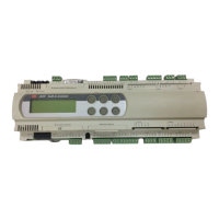
Standard Chiller/HP modulare per compressore a vite con driver CAREL
Cod.: +030221241 Rel. 1.0 dated 25 September 03
17
DESCRIPTION OF PARAMETER SCREEN MASTER
SLAVE
FACTORY
VALUE
USER
VALUE
RANGE MEASU-
REMENT
UNIT
Pump status in case of antifreeze alarm Gf M Pump ON Pump ON /Pump OFF
Solenoid-valve management set-point Gg M/S 80.0 0 to 999.9 °C
Solenoid-valve management differential Gg M/S 10.0 0 to 99.9 °C
Antifreeze heater set point Gh M/S 5.0 0 to 99.9 °C
Antifreeze heater differential Gh M/S 1.0 0 to 99.9 °C
Cycle reversing valve logic Gi M/S N.O. N.O. / N.C.
Type of freecooling control Gi M/S 0/10V ON-OFF/0-10V
Antifreeze temperature Gi M/S -2.0 -99.9 to 99.9 °C
Defrosting probe configuration Cj M/S Pressure
switches
Temperature
Pressure switches
Type of overall defrosting Cj M/S Simultaneous Simultaneous
Separate
Independent
CAREL EXV DRIVERS →
Driver 1 valve type F0 M/S Custom 0-11 (see page 8)
Enable driver 1 battery F0 M/S N. N/Y
Percentage relationship between Refrigerating power
and Driver 1 power
F1 M/S 60 0 to 100 %
Driver 2 valve type F2 M/S Custom 0-11 (see page 8)
Enable driver 2 battery F2 M/S N. N/Y
Percentage relationship between Refrigerating power and
Driver C2 power
F3 M/S 60 0 to 100 %
Driver 1 superheat set point during chiller operation F4 M/S 6.0 2.0 to 50.0 °C
Driver 1 dead band during chiller operation F4 M/S 0 0 to 9.9 °C
Driver 1 superheat set point during defrost. operation F5 M/S 6.0 2.0 to 50.0 °C
Driver 1 dead band during defrost. operation F5 M/S 0 0 to 9.9 °C
Driver 2 superheat set point during heat pump operation F6 M/S 6.0 2.0 to 50.0 °C
Driver 2 dead band during heat pump operation F6 M/S 0 0 to 9.9 °C
Driver 2 superheat set point during chiller operation F7 M/S 2.5 0.0 to 99.9
Driver 1 integral time during chiller operation F7 M/S 25 0 to 999 seconds
Driver 1 derivative time during chiller operation F7 M/S 2.0 0.0 to 99.9 seconds
Driver 2 proportional gain during defrost. operation F8 M/S 2.5 0.0 to 99.9
Driver 1 integral time during defrost. operation F8 M/S 25 0 to 999 seconds
Driver 1 derivative time during defrost. operation F8 M/S 2.0 0.0 to 99.9 seconds
Driver 2 proportional gain during heat pump operation F9 M/S 2.5 0.0 to 99.9
Driver 2 integral time during heat pump operation F9 M/S 25 0 to 999 seconds
Driver 2 derivative time during heat pump operation F9 M/S 2.0 0.0 to 99.9 seconds
Threshold for driver 1 low superheat protection
during chiller operation.
Fa M/S 4.0 -4.0 to 10.0 °C
Integral time for driver 1 low superheat protection
super heat in chiller operation
Fa M/S 1.0 0 to 25.5 seconds
Threshold for driver 1 low superheat protection
during defrosting operation.
Fb M/S 4.0 -4.0 to 10.0 °C
Integral time for low alarm protection super heat
driver 1 during defrost operation
Fb M/S 1.0 0 to 25.5 seconds
Threshold for driver 2 low super heat during pump
operation
Fc M/S 4.0 -4.0 to 10.0 °C
Threshold integral time for driver 2 low super
protection during heat pump operation
Fc M/S 1.0 0 to 25.5 seconds
Threshold for LOP protection during chiller operation Fd M/S -40.0 -70.0 to 50.0 °C
Threshold Integral time for LOP protection during
chiller. operation
Fd M/S 4.0 0 to 25.5 seconds
Threshold for LOP protection during heat pump operation Fe M/S -40.0 -70.0 to 50.0 °C
Threshold integral time for LOP protection during heat
pump operation
Fe M/S 4.0 0 to 25.5 seconds
Threshold for LOP protection during defrost. operation Ff M/S -40.0 -70.0 to 50.0 °C
Integral time of threshold for LOP protection during
defrost. operation
Ff M/S 4.0 0 to 25.5 seconds
Delayed start MOP protection during chiller operation Fg M/S 30 0 to 500 seconds
Threshold for MOP protection during chiller operation Fg M/S 40.0 -50.0 to 99.9 °C
Threshold Integral time for LOP protection during
chiller. operation
Fg M/S 4.0 0 to 25.5 seconds
Delayed start MOP protection during heat pump operation Fh M/S 30 0 to 500 seconds
Threshold for MOP protection during heat pump operation Fh M/S 40.0 -50.0 to 99.9 °C
Threshold integral time for MOP protection during
heat pump operation
Fh M/S 4.0 0 to 25.5 seconds
Delayed start MOP protection during chiller operation Fi M/S 30 0 to 500 seconds
Threshold for MOP protection during chiller operation Fi M/S 40.0 -50.0 to 99.9 °C
Threshold Integral time for LOP protection during
chiller. operation
Fi M/S 4.0 0 to 25.5 seconds
Threshold for condensation high temperature
protection during chiller operation
Fj M/S 75.0 0 to 99.9 °C

 Loading...