Standard Chiller/HP modulare per compressore a vite con driver CAREL
Cod.: +030221241 Rel. 1.0 dated 25 September 03
42
Example
Control set point 12.0ºC
Free Cooling Differential 4.0ºC
Free Cooling valve % threshold 40%
Condensation inverter % threshold: 80%
Proportional area for control of Free Cooling valve = 10.0 - 11.6 ºC
Control Set point - Free Cooling Differential/2 = 10.0ºC
Maximum % threshold for valve opening = 1.6ºC
Proportional area for control of condensation inverter = 13.2 - 16.0 ºC
Control Set point - Free Cooling Differential/2 = 10.0ºC
Control Set point - Free Cooling Differential/2 + inverter speed minimum % Threshold = 13.2ºC
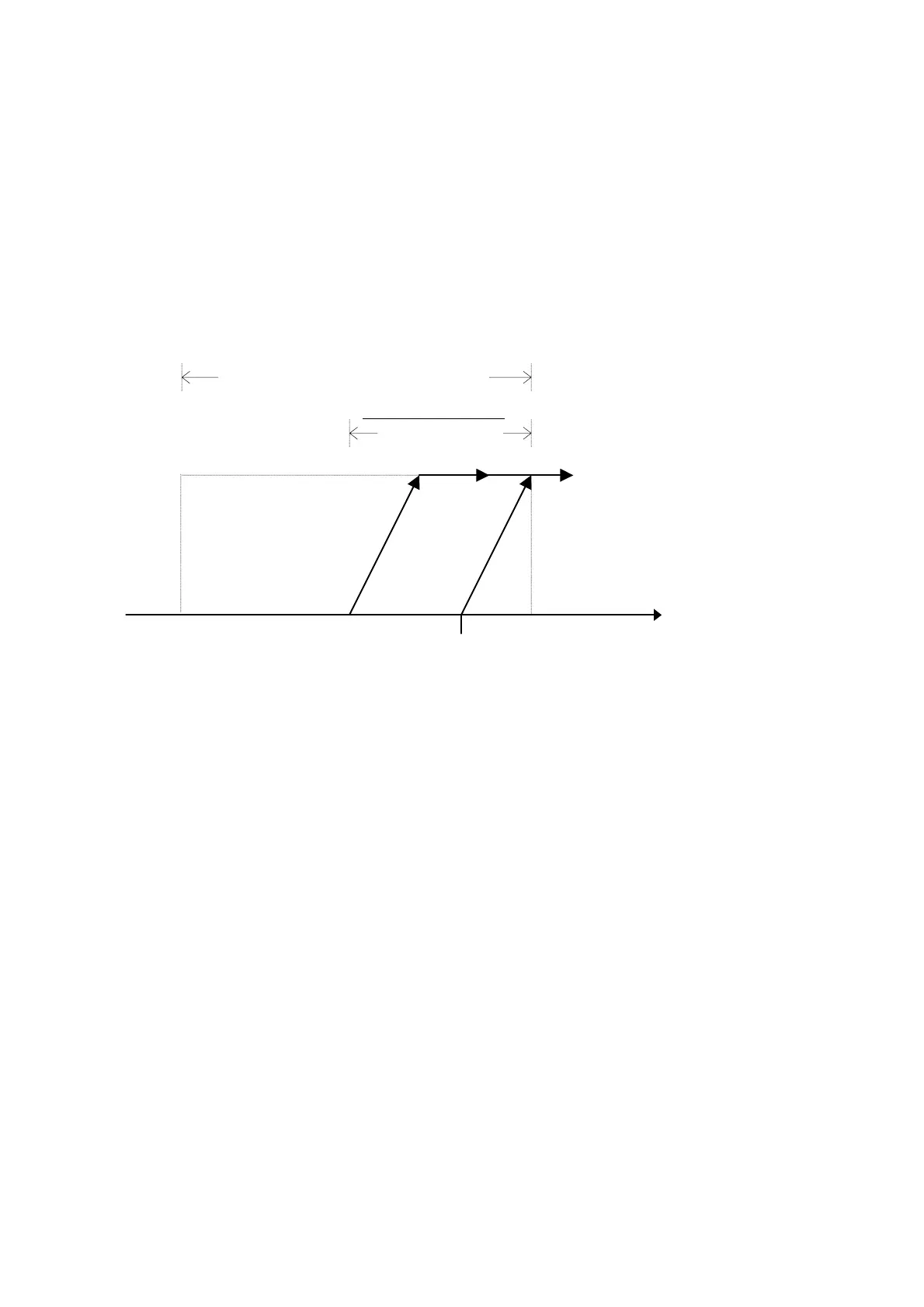
19.10.2 Proportional + integral control
Evaporator Outlet
Temperature
Valve opening max
% threshold.
Inverter speed
minimum % threshold
Free Cooling Differential
0 Volt
10 Volt
Valve 0 to 10V
Free Cooling
Inverter Ramp 0 to 10
V
set point Free
Cooling
Free Cooling differential
2
The devices, whether they are valve or fans, will be activated in the second half of the control differential through the effect of the integrating
control. This activation will be constrained by the set integrative constant. The greater the value assigned to the integration time, the slower the
system's response.

 Loading...


