CAREL INDUSTRIES HQs
Via dell’Industria, 11 - 35020 Brugine - Padova (Italy)
Tel. (+39) 0499716611 – Fax (+39) 0499716600 – http://www.carel.com – e-mail: carel@carel.com
+0500086IE- rel. 2.0 - 11.06.2014
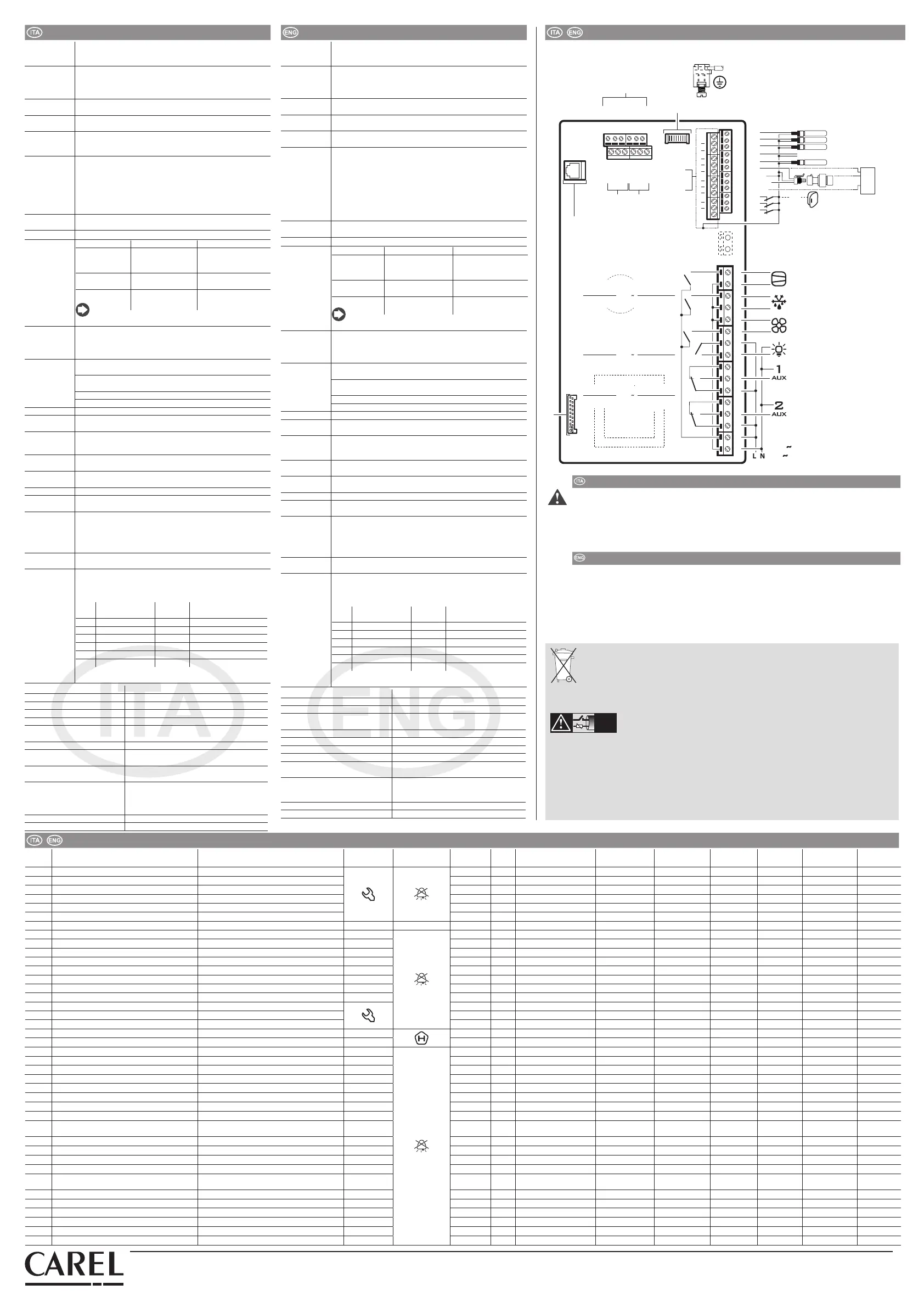
Schema di collegamento /
Wiring diagram
to remote terminal display
all GND
terminals
24 Vac
to graphic
terminal display
FieldBus BMS
R6
R5
R4
R3
R2
R1
230 V
20 A max
EN60730-1
UL 873
250 V
R5 - R6
12 (10) A
12 A res. 2HP
12FLA 72 LRA
to LED display board
CAREL NTC, PT1000
CAREL NTC, PT1000
CAREL NTC, PT1000
CAREL NTC, analog input 0 to 10 Vdc
B5 analog
input
(4 to 20 mA)
OUT
M
+V
0 to 5 Vdc
DI1
(**)
Door switch
B3
B2
B1
48 47 46 45 44 43
49 50 51 52 53 54
VL
GND
GND
Rx/Tx+
Rx/Tx-
GND
Rx/Tx+
Rx/Tx-
GND
Rx/Tx+
Rx/Tx-
GND
Y1
B4
B5
DI1
DI2
DI3
GND
5 VREF
+ Vdc
30
29
28
31
42
27
26
25
21
20
19
18
17
16
15
14
13
12
11
10
9
8
7
6
5
4
3
2
1
24
23
22
analog output (0 to 10 Vdc)
EN60730-1
UL 873
250 V
R3 - R4
10 A res.
5 (3) A
10 A res. 5FLA
18 LRA
EN60730-1
UL 873
250 V
R1 - R2
8 (4) A N.O.
8 A res. 2FLA
12 LRA
CMP
DEF
FAN
LIGHT
HACCP – ATTENZIONE -
WARNING
I programmi di Sicurezza Alimentare basati su procedure di tipo HACCP e più in genere alcune norma-
tive nazionali, richiedono che i dispositivi utilizzati per la conservazione degli alimenti siano sottoposti a
verifiche periodiche per garantire che gli errori di misura siano entro i limiti ammessi per l’applicazione di
utilizzo. Quando la misura della temperatura è rilevante per la Sicurezza Alimentare, andranno utilizzate
esclusivamente le sonde di temperatura suggerite da Carel. Ulteriori indicazioni sono riportate nel manuale
per quanto riguarda le caratteristiche tecniche, la corretta installazione e la configurazione del prodotto
HACCP –
WARNING
The Food Safety programs based on HACCP procedures and on certain national standards, require that
the devices used for food preservation are periodically checked to make sure that the measuring errors are
within the allowed limits of the application of use. When the temperature measurement is important for
food safety, only the temperature probes suggested by Carel must be used. The manual contains further
indications regarding technical feature, proper installation and confi guration of the product.
Tabella allarmi /
Alarms table
Cod.
display
Causa dell’allarme
Cause of the alarm
Display icon
flashing
Display button
flashing
Alarm relay Buzzer Reset PD valve Compressor Defrost Evaporator
fans
Condenser fans Continuous
cycle
rE Sonda virtuale di regolazione guasta
Virtual control probe fault
ON ON automatic duty setting(c4) duty setting(c4) - - - -
E0 Sonda B1 guasta
Probe B1 fault
ON ON automatic duty setting(c4) duty setting(c4) - - - -
E1 Sonda B2 guasta
Probe B2 fault
ON ON automatic - - - - - -
E2 Sonda B3 guasta
Probe B3 fault
ON ON automatic - - - - - -
E3 Sonda B4 guasta
Probe B4 fault
ON ON automatic - - - - - -
E4 Sonda B5 guasta
Probe B5 fault
ON ON automatic
--- - - OFF OFF automatic - - - - - -
LO Allarme bassa temperatura
Low temperature alarm
- ON ON automatic - - - - - -
HI Allarme alta temperatura
High temperature alarm
- ON ON automatic - - - - - -
IA Allarme immediato da contatto esterno
Immediate alarm from external contact
- ON ON automatic duty setting (A6) duty setting(A6) - - - -
Pd Allarme tempo massimo Pump Down
Maximum pump down time alarm
- ON ON automatic - - - - - -
LP Allarme di bassa pressione
Low pressure alarm
- ON ON automatic OFF OFF - - - -
AtS Autostart in pump down
Autostart in pump down
- ON ON automatic / manual - - - - - -
CHt Allarme alta temperatura condensatore
High condenser temperature alarm
- ON ON manual OFF OFF - - - -
dor Allarme porta aperta per troppo tempo
Door open for too long alarm
- ON ON automatic - - - - - -
Etc Real time clock guasto
Real time clock fault
OFF OFF automatic / manual - - - - - -
EE Errore eeprom parametri macchina
Unit parameter EEPROM error
OFF OFF automatic OFF OFF not featured OFF OFF not featured
EF Errore Eeprom parametri di funzionamento
Operating parameter EEPROM error
OFF OFF automatic OFF OFF not featured OFF OFF not featured
HA Allarme HACCP di tipo HA
Type HA HACCP alarm
- OFF OFF manual - - - - - -
HF Allarme HACCP di tipo HF
Type HF HACCP alarm
-
OFF OFF manual - - - - - -
LoG Scarico temperature registrate non riuscito
Temperature downloload failed
-
OFF ON automatic
- - - - - -
uPL Carico parametri non riuscito
Parameters upload failed
-
OFF ON automatic
- - - - - -
dnL Scarico parametri non riuscito
Parameters download failed
-
OFF ON automatic
- - - - - -
SHA Protezione basso Surriscaldamento
Low superheat protection
-
OFF ON automatic OFF OFF - - - -
LOA Protezione LOP
LOP protection
-
OFF ON automatic OFF OFF - - - -
MOA Protezione MOP
MOP protection
-
OFF ON automatic OFF OFF - - - -
EEA Guasto motore valvola
Valve motor fault
-
OFF ON automatic OFF OFF
LSA Superamento soglia e time-out
Threshold and timeout exceeded
-
OFF ON automatic OFF OFF - - - -
Hit Protezione alta temperatura cond. attivata
High condensing temperature protection
activated
-
OFF ON automatic OFF OFF - - - -
ES1 Guasto sonda S1 o superamento set
Probe S1 fault or set point exceeded
-
OFF ON automatic OFF OFF - - - -
ES2 Guasto sonda S2 o superamento set
Probe S2 fault or set point exceeded
-
OFF ON automatic OFF OFF - - - -
ES3 Guasto sonda S3 o superamento set
Probe S3 fault or set point exceeded
-
OFF ON automatic OFF OFF - - - -
ES4 Guasto sonda S4 o superamento set
Probe S4 fault or set point exceeded
-
OFF ON automatic OFF OFF - - - -
bAt
Batteria scarica o guasta o conness. elettrica
interrotta
Battery discharged or faulty or electrical
connection interrupted
-
OFF ON automatic OFF OFF - - - -
EEE Errore EEPROM funz. e/o parametri
Operating and/or parameter EEPROM error
-
OFF ON automatic OFF OFF - - - -
EIC Chiusura valvola incompleta
Valve not closed completely
-
OFF ON automatic OFF OFF - - - -
EEC Chiusura valvola in emergenza
Valve closed in emergency
-
OFF ON automatic OFF OFF - - - -
EFu Errore compatibilità FW (>=5.0)
FW compatibility error (>=5.0)
-
OFF ON automatic OFF OFF - - - -
ECn Errore configurazione
Configuration error
-
OFF ON automatic OFF OFF - - - -
ELE EVD offline
EVD offline
-
OFF ON automatic OFF OFF - - - -
Smaltimento del prodotto: Il prodotto deve essere oggetto di raccolta dierenziata in conformità alle
normative locali vigenti in materia di smaltimento.
______________________________________________________________________________________
Disposal of the product: The appliance (or the product) must be disposed of separately in compliance
with the local standards in force on waste disposal.
NO POWER
& SIGNAL
CABLES
TOGETHER
READ CAREFULLY IN THE TEXT!
ATTENZIONE: separare quanto più possibile i cavi delle sonde e degli ingressi digitali dai cavi dei ca-
richi induttivi e di potenza per evitare possibili disturbi elettromagnetici. Non inserire mai nelle stesse
canaline (comprese quelle dei quadri elettrici) cavi di potenza e cavi di segnale.
WARNING:
separate as much as possible the probe and digital input signal cables from the cables
carrying inductive loads and power cables to avoid possible electromagnetic disturbance. Never run
power cables (including the electrical panel wiring) and signal cables in the same conduits
Carel si riserva la possibilità di apportare modiche o cambiamenti ai propri prodotti senza alcun preavviso.
Carel reserves the right to modify the features of its products without prior notice.
Caratteristiche tecniche
Alimentazione
Mod. 230V
Mod. 24V
Tensione 230 V~ (+10/-15%), 50/60 Hz; Potenza 18 VA, 100 mA~ max.
Tensione 24 V~ (+10/-15%), 50/60 Hz; Potenza 18 VA, 1A~ max.
Isolamento
garantito dall’
alimentazione
230 V
Isolamento rispetto alla bassissima tensione: rinforzato, 6 mm
in aria, 8 mm superficiali, 3750V. Isolamento rispetto alle uscite
relè: principale, 3 mm in aria, 4 mm superficiali, 1250 V.
Ingressi
analogici
B1, B2, B3: NTC, PT1000 (±3%); B4: NTC, 0...10Vdc (±3%); B5:
0...5Vdc raziometrico (±3%), 4...20mA (±3%)
Uscita
analogica
Y1: 0...10Vdc (10mA max, ±5%)
Nota: Nell’installazione tenere separati i collegamenti di alimen-
tazione e dei carichi dai cavi delle sonde, ingressi digitali e
supervisore.
Tipo sonda
NTC std. CAREL
NTC HT
PT1000 std.
CAREL
10 kΩ a 25°C, range da -50°C a 90°C; errore di misura: 1°C nel ran
-
ge da -50°C a +50°C; 3°C nel range da +50°C a +90°C
50 kΩ a 25°C, range da 0°C a 150°C; errore di misura: 1,5°C nel ran
-
ge da 0°C a +115°C; 4°C nel range da +115°C a +150°C
1000Ω a 0°C, range da –50°C a +90°C; errore di misura 3°C nel
range da –50°C a 0°C; 5°C nel range da 0°C a +90°C
Alimentazione
sonde attive
+Vdc: 12V+-30%, 25mAmax; 5VREF: 5V+-2%
Uscite relè Rating applicabili a seconda del tipo di relè
Tipo relè EN60730 -1 (250 V ~) UL 873 (250 V ~)
8A (AUX1,AUX2) 8 (4)A su N.O.; 6 (4)A
su N.C.; 2 (2)A su N.C. e
N.O. (100000 cicli)
8A resistivi 2FLA 12LRA,
C300 (30000 cicli)
16A (LIGHT, FAN) 10A resistivi, 5 (3)A
(100000 cicli)
10A resistivi, 5FLA
18LRA (30000 cicli)
30A (COMP, DEF) 12 (10)A (100000
cicli)
12A resistivi, 2HP, 12FLA
72LRA (30000 cicli)
Nota: La somma delle correnti dei carichi COMP, DEF, FAN
accesi contemporaneamente non dovrà superare i 20A.
Isolamento Isolamento rispetto alla bassissima tensione: rinforzato; 6 mm
in aria, 8 superficiali; 3750 V
Isolamento tra le uscite relè indipendenti: principale; 3 mm in
aria, 4 superficiali; 1250 V
Connessioni Sezione conduttori per ingressi e uscite analogiche, ingressi
digitali, seriali: da 0,5 a 2,5mm2 (da 20 a 13 AWG);
Sez. conduttori per alimentazione e carichi: da 1,5 a 2,5 mm
2
(da
15 a 13 AWG)
Connessioni seriali: utilizzare cavi schermati
Lunghezza massima dei cavi: 10m
Contenitore Plastico: dimensioni 200 x 100 X 190 mm
Montaggio A parete (con contenitore plastico): mediante viti di fissaggio
scheda frontale
Display Display LED: 3 e 4 digit, visualizzazione da -99 a 999; stati di
funzionamento indicati con led e icone grafiche ricavate sul
policarbonato applicato al contenitore plastico
Tastiera 10 tasti su tastiera a membrana in policarbonato applicato al con-
tenitore plastico
Orologio con bat-
teria tampone
Disponibile
Buzzer Disponibile in tutti i modelli
Orologio Precisione: ±100 ppm; Batteria: tipo “bottone” al litio cod.
CR2430 tensione: 3Vdc (dimensioni 24x3 mm)
Seriali dispo-
nibili
3 tipi: pLAN, BMS, Fieldbus
pLAN: Driver HW RS485, jack telefonico (presente a seconda del
modello) e morsetti a vite
BMS: Driver HW RS485, morsetti a vite
Fieldbus: Driver HW RS485, morsetti a vite
USB Tipo: Host (connettore tipo A); alimentazione 5Vdc, max assor-
bimento: 100mA (low power devices)
Condizioni di
funzionamento
Scheda nuda: -10T65°C; <90% U.R. non condensante
Con contenitore plastico: -10T50°C, <90% U.R. non condensante
Identificazione dei relè, tipo e massima corrente resistiva alla
temp. di funzionamento:
Relè Carico associato Tipo relè
Max corrente resistiva
applicabile
R1 (AUX2) 8A 8A
R2 (AUX1) 8A 8A
R3 (LIGHT) 16A 10A
R4 (FAN) 16A 10A
R5 (DEF) 30A 12A
R6 (COMP) 30A 12A
Nota: la somma delle correnti dei carichi (COMP), (DEF), (FAN)
accesi contemporaneamente non dovrà superare i 20A
Condizioni di immagazzinam. -20T70°C, < 90% U.R. non condensante
Grado di protezione frontale Con contenitore plastico: IP65
Inquinamento ambientale 2, situazione normale
PTI dei materiali di isolamento Circuiti stampati 250, plastica e materiali isolanti 175
Categoria di resistenza al fuoco Categoria D
Classe di protezione contro la
sovratensione
Categoria II
Tipo di azione e sconnessione Contatti relè 1 B (microdisconnessione)
Costruzione del dispositivo di
comando
Dispositivo di comando incorporato, elet-
tronico
Classific. secondo la protezione
contro le scosse elettriche
Classe II senza morsetto di terra
Classe I con morsetto di terra
Dispositivo destinato ad essere
tenuto in mano o incorporato
in apparecchiatura destinata ad
essere tenuta in mano
No
Classe e struttura del software Classe A
Pulizia frontale del controllo utilizzare solo detergenti neutri ed acqua
Technical specications
Power supply
230 V model
24 V model
Voltage 230 V~ (+10/-15%), 50/60 Hz; Power 18 VA, 100 mA~ max.
Voltage 24 V~ (+10/-15%), 50/60 Hz; Power 18 VA, 1A~ max.
Insulation
guaranteed
from the 230V
power supply
Insulation from extra low voltage parts: reinforced, 6 mm cle
-
arance, 8 mm creepage, 3750V. Insulation from relay outputs:
basic, 3 mm clearance, 4 mm creepage, 1250 V.
Analogue
inputs
B1, B2, B3: NTC, PT1000 (±3%); B4: NTC, 0 to 10 Vdc (±3%); B5: 0
to 5 Vdc ratiometric (±3%), 4 to 20 mA (±3%)
Analogue
output
Y1: 0 to 10 Vdc (10 mA max, ±5%)
Note: In the installation, separate the power and load connections
from the probe, digital input and supervisor cables.
Probe type
Std. CAREL NTC
NTC HT
Std. CAREL
PT1000
10 kΩ at 25°C, range from -50°C to 90°C; measurement error: 1°C
in the range from -50°C to +50°C; 3°C in the range from +50°C to
+90°C
50 kΩ at 25°C, range from 0°C to 150°C; measurement error: 1.5°C
in the range from 0°C to +115°C; 4°C in the range from +115°C to
+150°C
1000Ω to 0°C, range from –50°C to +90°C; measurement error 3°C
in the range from –50°C to 0°C; 5°C in the range from 0°C to +90°C
Power to active
probes
+Vdc: 12 V+-30%, 25 mA max; 5 V REF: 5V+-2%
Relay outputs Applicable rating depending on the type of relay
Relay type EN60730 -1 (250 V ~) UL 873 (250 V ~)
8A (AUX1,AUX2) 8 (4)A on N.O.; 6 (4)A
on N.C.; 2 (2)A on N.C. &
N.O. (100000 cycles)
8A resistive 2FLA 12LRA,
C300 (30000 cycles)
16A (LIGHT, FAN) 10A resistive, 5 (3)A
(100000 cycles)
10A resistive, 5FLA 18LRA
(30000 cycles)
30A (COMP, DEF) 12 (10)A (100000
cycles)
12A resistive, 2HP, 12FLA
72LRA (30000 cycles)
Note: The sum of the current to the loads (COMP, DEF,
FAN) when on at the same time must never exceed 20 A.
Insulation
Insulation from extra low voltage parts: reinforced; 6 mm clea-
rance, 8 mm creepage; 3750 V
Insulation between independent relay outputs: main; 3 mm
clearance, 4 mm creepage; 1250 V
Connections Wire cross-section for analogue inputs and outputs, digital
inputs, serial: from 0.5 to 2.5mm
2
(from 20 to 13 AWG);
Wire cross-section for power supply and loads: from 1.5 to 2.5
mm
2
(from 15 to 13 AWG)
Serial connections: use shielded cables
Maximum cable length: 10m
Case Plastic: dimensions 200 x 100 x 190 mm
Assembly Wall mounting (with plastic case): by fastening screws through
front board
Display LED display: 3 and 4 digits, display from -99 to 999; operating status
indicated by LEDs and graphic icons visible on polycarbonate
applied to the plastic case
Keypad 10 buttons on membrane polycarbonate keypad applied to the
plastic case
Clock with bat
-
tery backup
Available
Buzzer Available on all models
Clock Precision: ±100 ppm; battery: lithium button battery type
CR2430 voltage: 3 Vdc (dimensions 24x3 mm)
Serial port
available
3 types: pLAN, BMS, Fieldbus
pLAN: RS485 HW driver, telephone jack (available according to
the model) and screw terminals
BMS: RS485 HW driver, screw terminals
Fieldbus: RS485 HW driver, screw terminals
USB Type: Host (type A connector); power supply 5 Vdc, max cur
-
rent: 100 mA (low power devices)
Operating con
-
ditions
Open board: -10T65°C; <90% RH non-condensing
With plastic case: -10T50°C, <90% RH non-condensing
Identification of relays, type and maximum resistive current at
operating temp.:
Relay Associated load Relay type
Max applicable resistive
current
R1 (AUX2) 8A 8A
R2 (AUX1) 8A 8A
R3 (LIGHT) 16A 10A
R4 (FAN) 16A 10A
R5 (DEF) 30A 12A
R6 (COMP) 30A 12A
Note: the sum of the current to the loads (COMP), (DEF), (FAN)
when on at the same time must not exceed 20 A
Storage conditions -20T70°C, < 90% RH non-condensing
Front panel ingress protection With plastic case: IP65
Environmental pollution 2, normal situation
PTI of the insulating materials Printed circuits 250, plastic and insulating
materials 175
Category of resistance to fire Category D
Class of protection against voltage surge Category II
Type of action and disconnection Relay contacts 1 B (microswitching)
Construction of the control device Integrated electronic control device
Classification according to protec
-
tion against electric shock
Class II without earth terminal
Class I with earth terminal
Device designed to be hand-held
or integrated into equipment desi
-
gned to be hand-held
No
Software class and structure Class A
Cleaning of controller front panel Only use neutral detergents and water
 Loading...


