EN
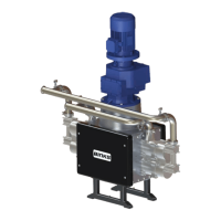
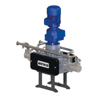
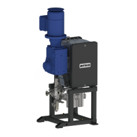
The Pump Units are designed for location in Zone 1 Hazardous areas, ATEX Category 2.(Motor Gearbox
Dependant)
Electrical connections must be in accordance with Local Regulations for installation in Hazardous Areas.
It is recommended that a Local Control Box is positioned in close proximity to the pump, as a convenient local
Start / Stop facility and Junction box.
The main Pump Control Panel must be positioned within an Electrically Safe Area.
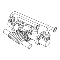
A Pressure switch [and/or Pressure relief valve (fitted to pump as standard)] must be connected to the outlet
manifold port and set to stop the pump (or relieve the fluid pressure) in the event of the system overpressure
e.g. blocked paint filter, otherwise Pump warranty may be invalidated.
This is necessary to protect the Pump mechanics from overload.A sensor manifold to mount a pressure switch
and pressure sensor is available, see accessories.
It is recommended that the switch setting is set to 1 bar [14.5 psi] above the maximum required pressure.
The maximum pressure setting the Pressure Switch should be set to is 20 bar [305 psi].
The Pressure Switch is classified as simple apparatus and as such should be electrically connected as part of an
intrinsically safe electrical circuit.
he Pressure Switch should be wired as a Normally Closed contact (fail safe) and be hard wired to stop the motor
on operation, to minimise response time.
INSTALLATION
77-3330 R1.3 6/36 www.carlisleft.com