17 - CONTROL CABINET WITH ELECTRONIC BOARD OPTION
Function
■ Protects and controls the motors. The control electronic board makes it possible to control the temperature or pressure, monitor
the operating parameters, communicate with certain chillers, diagnose and store faults and communicate with the remote control
console, additional boards or a BMS.
Power supply
■ See connection sheet or wiring diagram supplied with the cabinet.
Limits of use
■ Ambient air:
- Storage temperature: -40/+60°C
- Operating temperature: -25/+55°C
Components
■ Packing boxes are provided for the installer on the base of the cabinet.
■ A lockable isolator switch is used as an emergency stop.
■ Protection against short circuit provided by 1 or 2 three-pole circuit breakers (ICC = 10 KA)
■ Protection against overload: thermal cut-out wiring on electronic board.
■ 1 x 230 V switch per stage.
■ 1 Electronic board.
■ 1 x console with LCD screen optional for condenser.
■ Fluid temperature sensor (drycooler): tted on the outlet pipe (control sensor).
Electrical connection
■ Before making any connection, check that the machine's disconnect switch is open.
■ The cabinet is connected to the motors and mounted on the front of the unit, on the inlet manifold side.
■ For electrical connection, refer to the connection sheet or wiring diagram supplied with the cabinet.
■ The cables to use for the power connection must be made from copper. If cables made from other materials, such as aluminium,
are used, bimetallic terminals and connectors or intermediate terminals must be used.
■ The electrical connections are to be made as follows:
- Check that the power supply cable is not powered on before connecting the power circuit on the disconnect switch.
- Connection of the protective conductor to the earth terminal.
- Connection for automatic operation control
- Connection for changing the setpoint.
- Connection for fan forced operation
■ Outdoor temperature sensor (drycooler):
- The machine must be installed to enable the outdoor temperature sensor to be positioned on the nearest north façade of the
building. Failing this, the sensor must be positioned on the north face of the unit, away from any air ows (e.g. fan).
If none of these criteria can be met, the customer must put a met mast in place. (Not supplied)
- The sensor cable must be protected from any harmful external elements.
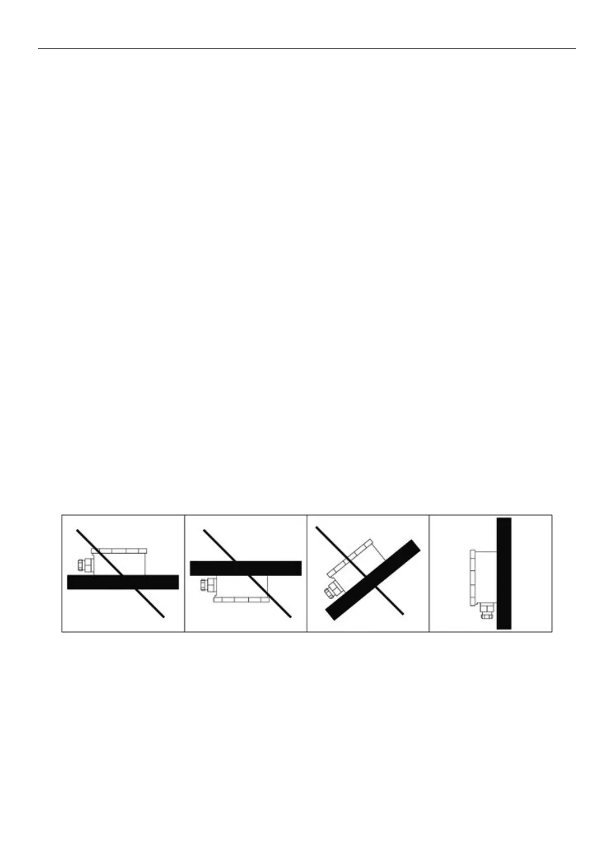
- Make sure the outdoor sensor is not exposed to direct sunlight, and place it in a vertical position:
Electronic board functions.
■ See the user manual for the electronic board.
17