EasyManua.ls Logo

Carrier 17/19EX User Manual

Carrier 17/19EX
437 pages
To Next Page IconTo Next Page
Page #1 background imageLoading...
Page #1 background image
17/19EX
50/60 Hz
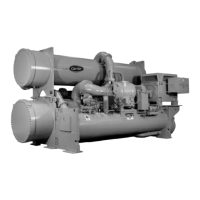
Centrifugal Liquid Chillers
with HFC-134a
Start-Up, Operation, and Maintenance Instructions
Manufacturer reserves the right to discontinue, or change at any time, specifications or designs without notice and
without incurring obligations.
PC 211 Catalog No. 531-715 9-95 Form 17/19EX-1SS Replaces: 19EX-1SS
Copyright
©
Carrier Corporation 1995
Safety Considerations
Centrifugal liquid chillers are designed to provide safe and reliable service when
operated within design specifications. When operating this equipment, use good
judgement and safety precautions to avoid damage to equipment and property or injury
to personnel.
Be sure you understand and follow the procedures and safety precautions contained
in the machine instructions as well as those listed in this guide.
®

Table of Contents

Question and Answer IconNeed help?

Do you have a question about the Carrier 17/19EX and is the answer not in the manual?

Carrier 17/19EX Specifications

General IconGeneral
BrandCarrier
Model17/19EX
CategoryChiller
LanguageEnglish

Summary

Safety Considerations

Refrigeration Cycle

Motor/Oil Refrigeration Cooling Cycle

Hermetic Machines (19 Series) Lubrication Cycle

Open-Drive Machines (17 Series) Lubrication Cycle

Controls

PIC System Components

Processor Module (PSIO)

Contains operating software, senses pressures/temperatures using transducers and thermistors.

Starter Management Module (SMM)

Initiates PSIO commands for starter functions; monitors starter inputs.

Local Interface Device (LID)

Operator interface for PSIO/CCN devices; input for set points, schedules, and options.

LID Operation and Menus

Alarms and Alerts

Indicates alarm (*) and alert (!) status; alarms shut down compressor; alerts notify operator.

PIC System Functions

Capacity Control

PIC modulates guide vanes based on chilled water temperature changes from control point.

Deadband

Tolerance on chilled water/brine temperature control point; PIC opens/closes vanes until within tolerance.

Safety Controls

Demand Limiting

Occupancy Schedule

Capacity Override

High Discharge Temperature Control

Oil Sump Temperature Control

Condenser Freeze Prevention

Water/Brine Reset

Demand Limit Control, Option (Requires Optional 8-Input Module)

Surge Prevention Algorithm

Surge Protection

Lead/Lag Control

Lead/Lag Operation

Lead/Lag Chiller Configuration and Operation

Lag Chiller Start-Up Requirements

Lag Chiller Shutdown Requirements

Load Balancing

Ice Build Control

Ice Build Initiation

Start-Up/Recycle Operation

Termination of Ice Build

Attach to Network Device Control

Service Operation

Holiday Scheduling (Figure 24)

Related product manuals