12
vacuum (51.7 kPa absolute). In On mode, the unit will continue to
pumpout regardless of the suction (vacuum) pressure.
NOTE: During this operation, maintain water circulation through
the chiller cooler and condenser vessels to prevent tube freeze-up.
DISTILLING THE REFRIGERANT
Refrigerant vapor is transferred from the chiller cooler vessel or
pumpout storage tank through the pumpout condenser, condensed
to a liquid, and pumped to the chiller condenser vessel. During this
operation, water circulation must be maintained in the pump-out
condenser. Refrigerant impurities left in the chiller cooler vessel or
storage tank are then drained off. This operation can take from 4 to
14 hours, depending on the type and amount of refrigerant being
distilled.
The Pumpout and Refrigerant Transfer Procedures section gives
step-by-step instructions on performing these operations.
Pumpout and Refrigerant Transfer Procedures
PREPARATION
The 19XR chiller may come equipped with an optional pumpout
storage tank, pumpout system, or pumpout compressor. The re-
frigerant can be pumped for service work to either the chiller com-
pressor vessel or chiller condenser vessel by using the optional
pumpout system. If a pumpout storage tank is supplied, the refrig-
erant can be isolated in the storage tank. The following procedures
describe how to transfer refrigerant from vessel to vessel and per-
form chiller evacuation.
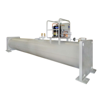
OPERATING THE OPTIONAL PUMPOUT UNIT (Fig. 9)
Oil should be visible in the pumpout unit compressor sight glass
under all operating conditions and during shutdown. If oil is low,
add oil as described under Maintenance section, page 17. The
pumpout unit control wiring schematic is detailed in Fig. 8.
To Read Refrigerant Pressures (during pumpout or leak testing):
1. The ICVC display on the chiller control panel is suitable for
determining refrigerant-side pressures and low (soft) vacuum.
To assure the desired range and accuracy when measuring
evacuation and dehydration, use a quality vacuum indicator
or manometer. This can be placed on the Schrader connec-
tions on each vessel by removing the pressure transducer.
2. To determine pumpout storage tank pressure, a 30 in. Hg vac-
uum -0-400 psi (-101-0-2769 kPa) gage is attached to the
storage tank.
3. Refer to Fig. 10 and 11 for valve locations and numbers.
Positive Pressure Chillers With Storage Tanks
In the Valve/Condition tables that accompany these instructions,
the letter “C” indicates a closed valve. Figures 9 and 10 show the
locations of the valves.
CAUTION
The power to the pumpout compressor oil heater must be on
whenever any valve connecting the pumpout compressor to
the chiller or storage tank is open. Leaving the heater off will
result in oil dilution by refrigerant and can lead to compressor
failure.
If the compressor is found with the heater off and a valve open
the heater must be on for at least 4 hours to drive the refriger-
ant from the oil. When heating the oil the compressor suction
must be open to a vessel to give the refrigerant a means to
leave the compressor.
CAUTION
Always run the chiller cooler and condenser water pumps and
always charge or transfer refrigerant as a gas when the chiller
pressure is less than 35 psig (241 kPa). Below these pressures,
liquid refrigerant flashes into gas, resulting in extremely low
temperatures in the cooler/condenser tubes and possibly caus-
ing tube freeze-up.
DANGER
During transfer of refrigerant into and out of the optional stor-
age tank, carefully monitor the storage tank level gage. Do not
fill the tank more than 90% of capacity to allow for refrigerant
expansion. Overfilling may result in damage to the tank or the
release of refrigerant which will result in personal injury or
death.
CAUTION
Do not mix refrigerants from chillers that use different com-
pressor oils. Compressor damage can result. The pumpout oil
separator comes pre-charged with 13 oz of ISO viscosity 220
POE (Polyol Ester) oil. The pumpout compressor is approved
for use with ISO viscosity 220 POE oil or ISO viscosity 68
POE oil. The pumpout compressor is also factory precharged
with oil.
CAUTION
Transfer, addition, or removal of refrigerant in spring-isolated
chillers may place severe stress on external piping if springs
have not been blocked in both up and down directions.
CAUTION
Always run chiller cooler and condenser water pumps and
always charge or transfer refrigerant as a gas when chiller ves-
sel pressure is less than 35 psig (241 kPa). Below these pres-
sures, liquid refrigerant flashes into gas, resulting in extremely
low temperatures in the cooler/condenser tubes and possibly
causing tube freeze-up.
CAUTION
The power to the pumpout compressor oil heater must be on
whenever any valve connecting the pumpout compressor to
the chiller or storage tank is open. Leaving the heater off will
result in oil dilution by refrigerant and can lead to compressor
failure.
If the compressor is found with the heater off and a valve open
the heater must be on for at least 4 hours to drive the refriger-
ant from the oil. When heating the oil the compressor suction
must be open to a vessel to give the refrigerant a means to
leave the compressor.
 Loading...