4
Step 3 —
Rig the Storage Tank
The complete 19XR system can be rigged as a single assembly.
See the rigging instructions on the label attached to the assembly.
Also refer to the rigging guide (Fig. 4), physical data in Tables 2
and 3, and contact surface and dimensions for the complete sys-
tem in Fig. 5. Lift the assembly only from the 4 points indicated in
the rigging guide. Each rigging cable must be capable of support-
ing the entire weight of the assembly.
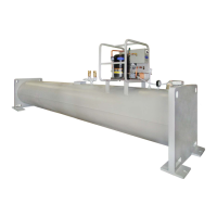
Fig. 1 — 19XR Positive Pressure Storage System
Fig. 2 — 19XR Pumpout Unit: Typical Chiller Mount
WARNING
Lifting the assembly from points other than those specified
may result in serious damage to the assembly and personal
injury. Rigging equipment and procedures must be adequate
for assembly. See Tables 2 and 3 for weights. (These weights
are broken down into pumpout unit and storage tank weights.
For the complete assembly weight, add all components
together.)
CONTACTOR
TERMINAL
STRIP
FUSES
TRANSFORMER
SWITCH
19XR PUMPOUT UNIT
19XR CONTROL BOX (INTERIOR)
a19-2444
FRAME
ASSEMBLY
CONTROL
PANEL
VALVE 2
VALVE 4
VALVE 5
VALVE 3
ENTERING
WATER
LEAVING
WATER CONDENSER
OIL
SEPARATOR
OIL
HEATER
COMPRESSOR
COMPRESSOR
CONTROL
BOX
VALVE
ASSEMBLY
CONDENSER
OIL
SEPARATOR
 Loading...