14
2. Push remaining liquid, followed by refrigerant vapor removal
from chiller.
a. To prepare for liquid push, turn off the pumpout con-
denser water. Place valves in the following positions:
b. Run the pumpout compressor in manual until all liquid is
pushed out of the chiller (approximately 45 minutes).
Close valves 2, 5, 7, and 10, then stop compressor.
c. Turn on pumpout condenser water.
d. Open valves 3 and 4, and place valves in the following
positions:
e. Run the pumpout compressor until the chiller pressure
reaches 35 psig (241 kPa), followed by turning off the
pumpout compressor. Warm chiller condenser water will
boil off any entrapped liquid refrigerant, and chiller pres-
sure will rise.
f. When chiller pressure rises to 40 psig (276 kPa), turn on
the pumpout compressor until the pressure reaches
35 psig (241 kPa) again; then turn off the pumpout com-
pressor. Repeat this process until the chiller pressure no
longer rises.
g. Start the chiller water pumps (condenser and cooler),
establishing water flow. At this point, turn on the pum-
pout compressor in auto until the vacuum switch is satis-
fied. This occurs at approximately 15 in Hg vacuum
(48 kPa absolute or 7 psia).
h. Close valves.
i. Turn off the pumpout condenser water.
Chillers With Isolation Valves
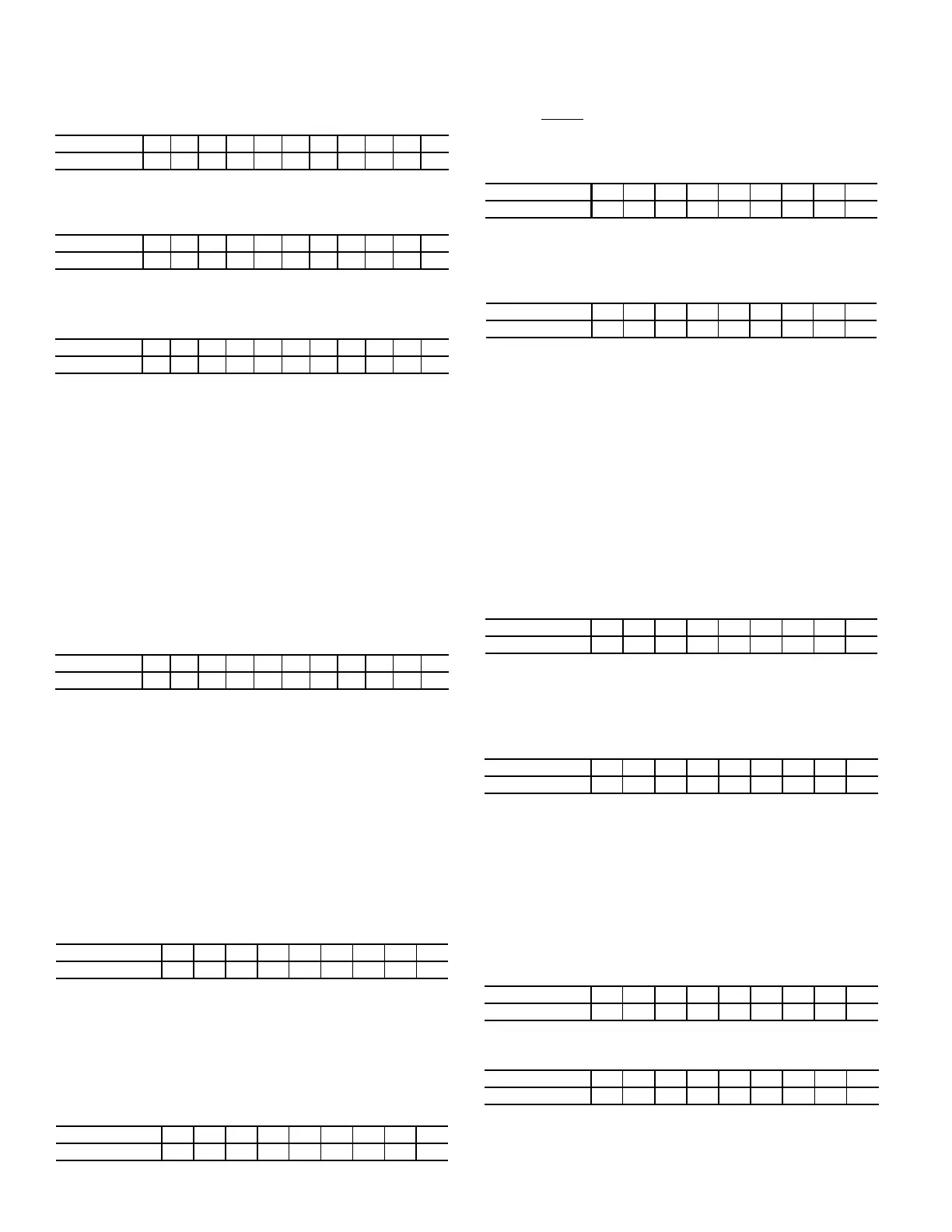
In the Valve/Condition tables that accompany these instructions,
the letter “C” indicates a closed valve.
The valves referred to in the following instructions are shown in
Fig. 9 and 11. The cooler/condenser vessels can be used for refrig-
erant isolation for certain service conditions when the isolation
valve package is specified.
Transfer Refrigerant from Cooler to Condenser
a. Turn off chiller water pumps and pumpout condenser
water supply (if applicable). It is assumed that the start-
ing point is as shown in the following table and that pres-
sures in both vessels are above 35 psig (241 kPa).
b. Keeping valves 7 and 8 closed, install charging hose
from liquid line charging valve 7 to valve 8 on the con-
denser float chamber. Evacuate or purge hose of non-
condensables. Note that this creates a flow path between
cooler and condenser that bypasses the linear float,
reducing the potential for damage during refrigerant
transfer.
c. Open valves 1A, 1B, 2, 5, and 8.
d. Turn on pumpout compressor, generating a refrigerant
pressure differential of 10 to 20 psi (69 to 138 kPa) to
push liquid out of the chiller cooler vessel.
e. Slowly
open valve 7 to allow liquid transfer. Rapid open-
ing of valve 7 can result in float valve damage.
f. When all liquid has been pushed into the chiller con-
denser vessel, close valve 8.
g. Turn off the pumpout compressor.
h. Close pumpout valves 2 and 5 while opening valve 3 and
4 to prepare for removal of remaining refrigerant vapor
in cooler vessel.
i. Turn on pumpout condenser water.
j. Turn on pumpout compressor. Turn on the chiller water
pump to establish water flow when the cooler refrigerant
pressure is 35 psig (241 kPa). The water pumps have to
be in operation whenever the refrigerant pressure is
equal to or less than 35 psig (241 kPa) to reduce the
potential of tube damage.
k. Run the pumpout compressor until the cooler pressure
reaches 35 psig (241 kPa), then turn off the pumpout
compressor. Warm chiller cooler water will boil off any
entrapped liquid refrigerant, and chiller pressure will
rise. Repeat this process until the chiller pressure no lon-
ger rises.
l. Run pumpout unit in auto until the vacuum switch is sat-
isfied; this occurs at approximately 15 in. Hg vacuum
(48 kPa absolute or 7 psia). Close valve 1A.
m. Monitor that cooler pressure does not rise (if it does, then
repeat previous step).
n. With service valve 1A closed, shut down pumpout com-
pressor (if still running).
o. Close remaining valves.
p. Remove charging hose between 7 and 8 (evacuate prior
to removal).
q. Turn off pumpout condenser water.
r. Turn off chiller water pumps, and lockout chiller com-
pressor.
Transfer Refrigerant from Condenser to Cooler
a. Turn off chiller water pumps and pumpout condenser
water supply (if applicable). It is assumed that the start-
ing point is as shown in the following table and that pres-
sures in both vessels are above 35 psig (241 kPa).
b. Set valves as shown below to allow the refrigerant to
equalize:
c. Turn on pumpout compressor, and develop a 10 to 20 psi
(69 to 138 kPa) refrigerant differential pressure between
the vessels.
VALVE 1A1B23456781011
CONDITION C C C
VALVE 1A1B23456781011
CONDITION CCCC CCC
VALVE 1A1B23456781011
CONDITION C C C C C
VALVE 1A1B23456781011
CONDITIONCCCCCCCCCC
VALVE 1A1B23457811
CONDITION CCCCCCCCC
VALVE 1A1B23457811
CONDITION C C C C
VALVE 1A1B23457811
CONDITION C C C C
VALVE 1A1B23457811
CONDITION C C C C
VALVE 1A1B23457811
CONDITION C C C C C
VALVE 1A1B23457811
CONDITION CCCCCCCCC
VALVE 1A1B23457811
CONDITION CCCCCCCCC
VALVE 1A1B23457811
CONDITION C CCCC
 Loading...