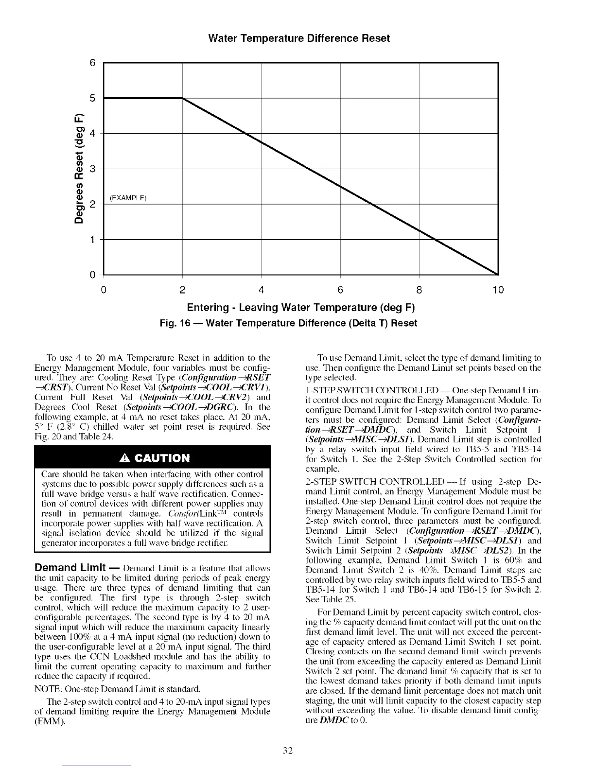
Water Temperature Difference Reset
LI..
"O
(/)
rr
g)
c_
3
(EXAMPLE)
2
1
0
0 4 10
Entering - Leaving Water Temperature (deg F)
Fig. 16 -- Water Temperature Difference (Delta T) Reset
To use 4 to 20 mA Temperature Reset in addition to the
Energy Management Module, four variables must be config-
ured. They are: Cooling Reset Type (Collfiguration _RSET
_CRST), CmTent No Reset Val (Setpoints _COOL _CR VI ),
Current Full Reset Val (Setpoints_COOL_CRV2) and
Degrees Cool Reset (Setpoints_COOL_DGRC). In the
following example, at 4 mA no reset takes place. At 20 mA,
5° F (2.8 ° C) chilled water set point reset is required. See
Fig. 20 and Table 24.
Cme should be taken when intell"acing with other control
systems due to possible power supply differences such as a
full wave bridge versus a half wave rectification. Connec-
tion of control devices with different power supplies may
result in pemlanent damage. Col_fhrtLink TM controls
incorporate power supplies with half wave rectification. A
signal isolation device should be utilized if the signal
generator incorporates a full wave bridge rectifiel:
Demand Limit -- Demand Limit is a feature that allows
the unit capacity to be limited during periods of peak energy
usage. There are three types of demand limiting that can
be configured. The first type is through 2-step switch
control, which will reduce the maximum capacity to 2 user-
configurable percentages. The second type is by 4 to 20 mA
signal input which will reduce the maximum capacity linearly
between 100% at a 4 mA input signal (no reduction) down to
the user-configurable level at a 20 mA input signal. The third
type uses the CCN I_adshed module and has the ability to
limit the cmTent operating capacity to maximum and further
reduce the capacity if required.
NOTE: One-step Demand Limit is stan&ud.
The 2-step switch control and 4 to 20-mA input signal types
of demand limiting require the Energy Management Module
(EMM).
To use Demand Limit, select the type of demand limiting to
use. Then configure the Demand Limit set points based on the
type selected.
1-STEP SWITCH CONTROLLED -- One-step Demand Lim-
it control does not require the Energy Management Module. To
configure Demand Limit for 1-step switch control two par_mle-
ters must be configured: Demand Limit Select (Configura-
tion _RSET--eDMDC), and Switch Limit Setpoint 1
(Seq_oints--+MISC--eDLSI). Demand Limit step is controlled
by a relay switch input field wired to TB5-5 and TB5-14
for Switch 1. See the 2-Step Switch Controlled section for
example.
2-STEP SWITCH CONTROLLED-- If using 2-step De-
mand Limit control, an Energy Management Module must be
installed. One-step Demand Limit control does not require the
Energy Management Module. To configure Demand Limit for
2-step switch control, three parameters must be configured:
Demand Limit Select (Configuration--eRSET--eDMDC),
Switch Limit Setpoint 1 (Se&oints--eMISC--eDLSI) and
Switch Limit Setpoint 2 (Se&oints--eMISC--eDLS2). In the
following exm_lple, Demand Limit Switch 1 is 60% and
Demand Limit Switch 2 is 40%. Demand Limit steps are
controlled by two relay switch inputs field wired to TB5-5 and
TB5-14 for Switch 1 and TB6-14 and TB6-15 for Switch 2.
See Table 25.
For Demand Limit by percent capacity switch control, clos-
ing the % capacity demand limit contact will put the unit on the
first demand limit level. The unit will not exceed the percent-
age of capacity entered as Demand Limit Switch 1 set point.
Closing contacts on the second demand limit switch prevents
the unit from exceeding the capacity entered as Demand Limit
Switch 2 set point. The demand limit % capacity that is set to
the lowest demand takes priority if both demand limit inputs
are closed. If the demtmd limit percentage does not match unit
staging, the unit will limit capacity to the closest capacity step
without exceeding the value. To disable demand limit config-
ure DMDC to 0.
32

 Loading...


