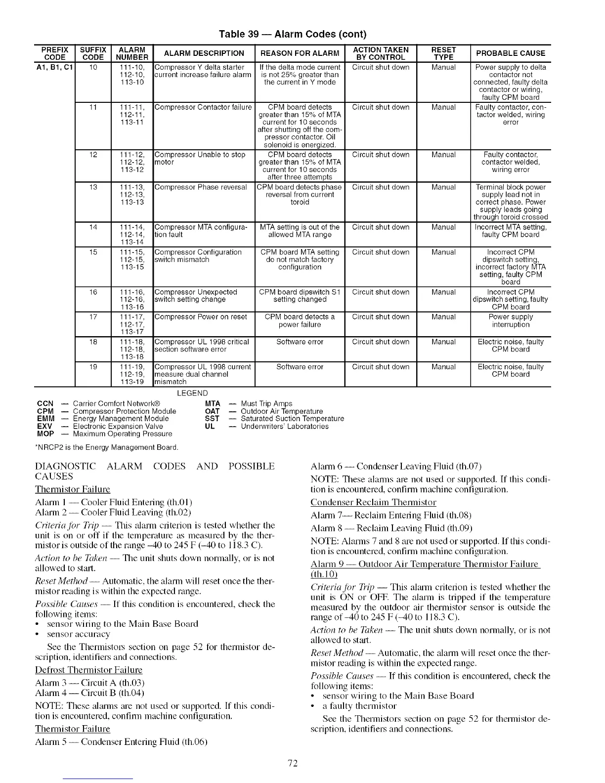
Table 39 -- Alarm Codes (cont)
PREFIX SUFFIX ALARM ALARM DESCRIPTION REASON FOR ALARM ACTION TAKEN RESET PROBABLE CAUSE
CODE CODE NUMBER BY CONTROL TYPE
A1, B1, C1 10 111-10, Compressor Y delta starter If the delta mode current Circuit shut down Manual Power supply to delta
112-10, 3urrent increase failure alarm is not 25% greater than contactor not
113-10 the current in Y mode connected, faulty delta
contactor or wiring,
faulty CPM board
11 111-11, Compressor Contactor failure CPM board detects Circuit shut down Manual Faulty contactor, con-
112-11, greater than 15% of MTA tactor welded, wiring
113-11 current for 10 seconds error
after shutting off the com-
pressor contactor. Oil
solenoid is energized.
12 111-12, Compressor Unable to stop CPM board detects Circuit shut down Manual Faulty contactor,
112-12, motor greater than 15% of MTA contactor welded,
113-12 current for 10 seconds wiring error
after three attempts
13 111-13, Compressor Phase reversal CPM board detects phase Circuit shut down Manual Terminal block power
112-13, reversal from current supply lead not in
113-13 toroid correct phase. Power
supply leads going
through toroid crossed
14 111-14, Compressor MTA configura- MTA setting is out of the Circuit shut down Manual Incorrect MTA setting,
112-14, tion fault allowed MTA range faulty CPM board
113-14
15 111-15, Compressor Configuration CPM board MTA setting Circuit shut down Manual Incorrect CPM
112-15, switch mismatch do not match factory dipswitch setting,
113-15 configuration incorrect factory MTA
setting, faulty CPM
board
16 111-16, Compressor Unexpected CPM board dipswitch Sl Circuit shut down Manual Incorrect CPM
112-16, switch setting change setting changed dipswitch setting, faulty
113-16 CPM board
17 111-17, Compressor Power on reset CPM board detects a Circuit shut down Manual Power supply
112-17, power failure interruption
113-17
18 111-18, Compressor UL 1998 critical Software error Circuit shut down Manual Electric noise, faulty
112-18, section software error CPM board
113-18
19 111-19, Compressor UL 1998 current Software error Circuit shut down Manual Electric noise, faulty
112-19, measure dual channel CPM board
113-19 mismatch
LEGEND
CCN -- Carrier Comfort Network@
CPM -- Compressor Protection Module
EMM -- Energy Management Module
EXV -- Electronic Expansion Valve
MOP -- Maximum Operating Pressure
MTA -- Must TripAmps
OAT -- Outdoor Air Temperature
SST -- Saturated Suction Temperature
UL -- Underwriters' Laboratories
*NRCP2 is the Energy Management Board.
DIAGNOSTIC ALARM CODES AND POSSIBLE
CAUSES
Thermistor Failure
Alarln 1-- Cooler Fluid Entering (th.01 )
Alarm 2 -- Cooler Fluid Leaving (th.02)
Criwriafbr Trip -- This _flarm criterion is tested whether the
unit is on or off if the temperature as measured by the ther-
mistor is outside of the range -40 to 245 F (-40 to 118.3 C).
Action to be Taken -- The unit shuts down normally, or is not
allowed to start.
Reset Method -- Automatic, the alarm will reset once the ther-
mistor reading is within the expected range.
Possible Causes -- If this condition is encountered, check the
following items:
• sensor wiring to the Main Base Board
• sensor accuracy
See the Thermistol.s section on page 52 for thermistor de-
scription, identifiers and connections.
Defrost Thermistor Failure
Alarm 3 -- Circuit A (th.03)
Alarm 4 -- Circuit B (th.04)
NOTE: These _flmms me not used or supported. If this condi-
tion is encountered, confirm machine configuration.
Thermistor Failure
Alarm 5 -- Condenser Entering Fluid (th.06)
Akum 6 -- Condenser Leaving Fluid (th.07)
NOTE: These alarlns are not used or supported. [f this condi-
tion is encountered, confirm machine configuration.
Condenser Reclaim Thermistor
Aimin 7-- Reclaim Entering Fluid (th.08)
Almm 8 -- Reclaim Leaving Fluid (th.09)
NOTE: Alarms 7 and 8 are not used or supported. If this condi-
tion is encountered, confirm machine configuration.
Alarm 9 -- Outdoor Air Temperature Thermistor Failure
CriWriajbr Trip -- This aku'm criterion is tested whether the
unit is ON or OFF. The alarm is tripped if the temperature
measured by the outdoor air thermistor sensor is outside the
range of_40 to 245 F (_4-0 to 118.3 C).
Action to be Taken -- The unit shuts down normally, or is not
allowed to st_ut.
Reset Method -- Automatic, the alarm will reset once the ther-
mistor reading is within the expected range.
Possible Causes -- If this condition is encountered, check the
following items:
• sensor wiring to the Main Base Board
• a faulty thermistor
See the Thermistors section on page 52 for thermistor de-
scripfion, identifiers and connections.
72

 Loading...


