O/W2
Y1
R
G
Y/Y2
W/W1
C
B
L
S1
S2
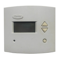
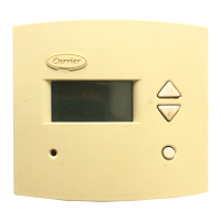
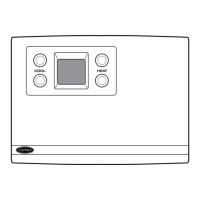
COMMERCIAL
THERMOSTAT
Y2
G
DO NOT USE
R
O
Y1
A
5
NOTE: Set DIP switch A tp ON.
Fig. 8 — Thermostat Wiring (50HQA)
A
B
C
D
ON
TEMPERATURE SENSOR
CONNECTION PINS
CONNECTION PINS
ON BOARD
RELAYS
DIP SWITCHES
A: ON=HP, OFF=AC
B: ON=2 STAGE, OFF=1 STAGE
C: ON=REMOTE SENSOR
OFF=OUTDOOR SENSOR
D: ON=AVERGING
OFF=NO AVERGING
W/W1
Y/Y2
G
R
Y1
O/W2
NOT USED
L
B
C
S2
S1
LEGEND
DIP — Dual In-Line Package
N/C — Normally Closed
N/O — Normally Open
NOTES:
1. All relays are N/O dry contacts except B which is N/C.
2. All relay contacts are rated for maximum load of 1.5 amps at 24 vac.
Fig. 9 — Commercial Programmable Thermostat Circuit Board Component Layout
50HQA
7
 Loading...


