34
APPLICATION DATA
UNIT SELECTION
The ceiling--suspended units are available as cooling only or heat
pump with electric heat. For most applications, the cooling load
dictates the size selection of the unit. Select equipment to either
match or be slightly less than anticipated peak load. This provides
better humidity control, fewer unit cycles, and less part--load
operation.
For units used in spaces with high sensible loads, base equipment
selection on unit sensible load, not on total anticipated load. Adjust
for anticipated room wet bulb temperature to avoid under--sizing
equipment.
UNIT MOUNTING (INDOOR)
Unit leveling -- For reliable operation, units should be level in all
planes. The 40QAC/QAQ ceiling--suspended fan coils may have
a slight pitch, but only toward the drain connection.
Clearance -- Refer to Fig. 9 for required CE clearances.
Unit location -- When selecting unit location, select a location that
will provide the best air circulation for the room.
the 40QAC/QAQ ceiling--suspended units should be mounted near
the ceiling and against a wall. The unit should be centered in the
room for best performance. Locating the unit on an outside wall
will make piping easier, but units can also be mounted away from a
wall if desired. If unit is mounted away from a wall, the rear panel
of the unit may need a field--supplied trim strip for improved
appearance. Locate the fan coil return over an area which is not
normally occupied for quietest operation. Do not block air
discharge for a minimum of 15 ft (4.6 m) to prevent dumping of
cold air and drafts.
Support -- The 40QAC/QAQ units are installed using the
mounting brackets supplied with the unit. The structure should
provide adequate support for the weight of the unit. Refer to the
Physical Data section in this document for fan coil weights.
Installation Template -- The 40QAC/QAQ units are furnished
with cardboard mounting templates to mark the location of the
mounting brackets, wiring, refrigeration line hole locations, and
indicate the location of ventilation air connections.
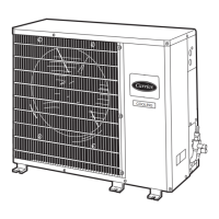
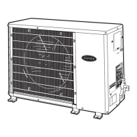
UNIT MOUNTING (OUTDOOR)
Unit leveling -- For reliable operation, units should be level in all
planes.
Clearance -- Minimum clearance, as shown in Fig. 8, must be
provided for airflow. The condensing units are designed for
free--blow application. Air inlets and outlets should not be
restricted.
Unit location -- A location which is convenient to installation and
not exposed to strong wind. If unit is exposed to strong winds it is
recommended that a wind baffle accessory be used.
A location which can bear the weight of outdoor unit and where
the outdoor unit can be mounted in a level position.
Mounting Pad -- The minimum mounting pad dimensions are
listed in the following table:
Unit Model
Minimum Mounting Pad Dimensions
f t . --- i n . ( m m )
38HDR018, 024, 030
38QRR018, 024
1’---11” X 3’---6”
(584.2 X 1066.8)
38HDR036, 048, 060
38QRR030, 036, 048, 060
2 ’ --- 0 ” X 4 ’ --- 2 ”
(609.6 X 1270)
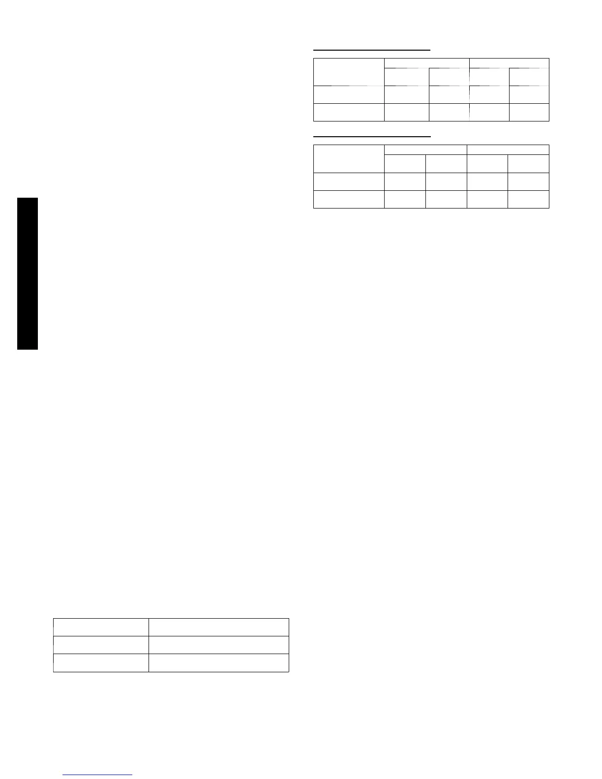
SYSTEM OPERATING CONDITIONS
Cooling operating range:
Maximum Minimum
DB
_F(_C)
WB
_F(_C)
DB
_F(_C)
WB
_F(_C)
Outdoor Unit
125
(51.7)
---
55
(12.8)
---
Indoor Unit
95
(35)
71
(21.7)
67
(19.4)
57
(13.9)
Heating operating range:
Maximum Minimum
DB
_F(_C)
WB
_F(_C)
DB
_F(_C)
WB
_F(_C)
Outdoor Unit
75
(23.9)
67
(19.4)
--- 2 0
(---28.9)
---
Indoor Unit
80
(26.7)
71
(21.7)
55
(12.8)
---
LOW AMBIENT OPERATION
Both cooling only and heat pumps will operate in cooling down to
55_F (12.8_C).
When equipped with a low ambient controller, the unit will operate
down to --20_F (--28.9_C).
For proper operation, a Winter Start Kit (bypasses the Low
Pressure Switch), a Crankcase Heater (prevents refrigerant
migration during compressor--off cycle), and a Wind Baffle should
also be installed. On heat pumps, a Winter Start Kit is not
required. An Isolation Relay to bypass the Low Ambient
Controller when unit is in heating mode is required.
METERING DEVICES
For cooling only on units, a TXV in the indoor unit controls the
refrigerant flow.
On heat pumps, an Accurator in the outdoor unit controls the
refrigerant flow in heating and another Accurator in the indoor unit
(except size 060, which has a TXV) controls the refrigerant flow in
cooling.
DRAIN CONNECTIONS
The drain connection on the ceiling--suspended unit is located on
the right hand side when facing the unit discharge.
When the unit is installed close to an outside wall, a downward
sloped condensate line can be used to dispose of the water (do not
trap condensate line). If this is not feasible, an accessory
condensate pump that can be installed inside the unit is available
and will provide up to 20 inches (508 mm) of lift. When using a
condensate pump, the drain pipe can be routed through the top of
the unit, if desired.
40QAC/38HDR -- 40QAQ/38QR
 Loading...