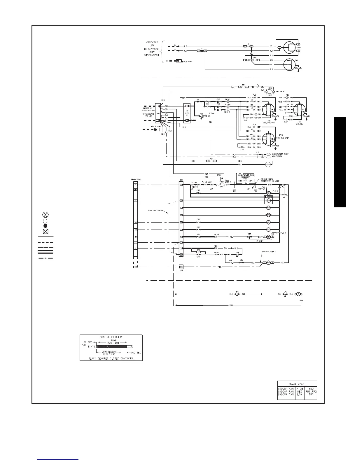
39
TYPICAL WIRING SCHEMATICS
NOTES:
1. If any of the original wire furnished must be replaced, it must be replaced with type 90° C
wire or its equivalent.
2. Wire in accordance with National Electrical Code, NEC) and all local codes.
3. Transformer is thermally protected and will reset automatically.
4. IFMs, OFM and COMP have internal thermal protection.
LEGEND
ASM — Air Sweep Motor
ASR — Air Sweep Relay
ASW — Air Sweep Switch
C—Contactor
CAP — Capacitor
COMP — Compressor
CR — Control Relay
CT — Current Transformer
DR — Delay Relay
EQUIP
GND
— Equipment Ground
FL — Fuse Link
FPT — Freeze Protection
Thermostat
FR — Fan Relay
FU — Fuse
HP — Heat Pump
HPS — High-Pressure Switch
HR — Heater Relay
HTR — Heater
HTT — Heater Temp
Thermostat
IFM — Indoor Fan Motor
LPS — Low-Pressure Switch
OFM — Outdoor-Fan Motor
OL — Overload
PDR — Pump Delay Relay
PL — Plug
PM — Pump Motor
PSS — Pump Shut-off Switch
TB — Terminal Block
TRAN — Transformer
Terminal (Marked)
Terminal (unmarked)
Splice
Terminal Block
Factory Wiring
Field Control Wiring
Field Power Wiring
Printed Circuit Board
Accessory or Optional
Wiring
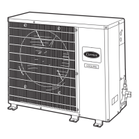
38HDR
40QAC
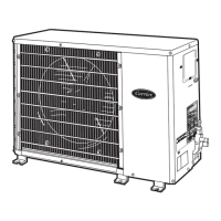
38HDR
40QAC
5. Use copper conductors only.
A12211
38HDR and 40QAC Cooling System Wiring Diagram
40QAC/38HDR -- 40QAQ/38QR
 Loading...