2
GENERAL
The 40VMU under ceiling/floor unit can be installed exposed
at the ceiling or mounted on the wall close to the floor. It is
ideal for corner or low-ceiling areas where soffit space is not
available for furred-in units.
The equipment is initially protected under the manufacturer’s
standard warranty; however, the warranty is provided under the
condition that the steps outlined in this manual for initial
inspection, proper installation, regular periodic maintenance,
and everyday operation of the unit be followed in detail. This
manual should be fully reviewed in advance before initial
installation, start-up and any maintenance. Contact your local
sales representative or the factory with any questions BEFORE
proceeding.
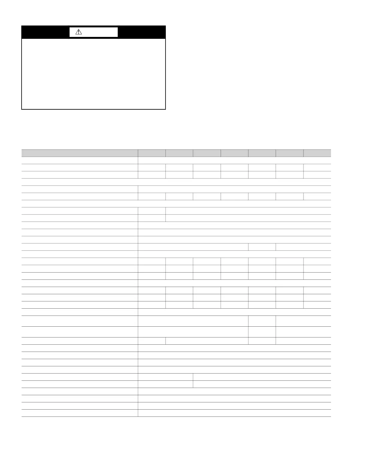
Table 1 lists physical data for each unit size. See Fig. 1 for the
model number nomenclature. Figures 2 and 3 show the unit
dimensions. Table 2 shows components that may or may not be
used for a particular installation.
Table 1 — 40VMU Physical Data
CAUTION
DO NOT re-use compressor oil or any oil that has been
exposed to the atmosphere. Dispose of oil per local codes
and regulations. DO NOT leave refrigerant system open to
air any longer than the actual time required to service the
equipment. Seal circuits being serviced and charge with
dry nitrogen to prevent oil contamination when timely
repairs cannot be completed. Failure to follow these
procedures may result in damage to equipment. For
information about replacement oil type and viscosity, see
the Installation, Start-Up, and Service Instructions for the
38VMAH and 38VMAR outdoor units.
UNIT 40VMU
012 015 018 024 030 036 048
POWER SUPPLY (V-Ph-Hz) 208/230-1-60
COOLING CAPACITY (Btuh)
12,000 15,000 18,000 24,000 30,000 36,000 48,000
HEATING CAPACITY (Btuh)
13,500 17,000 21,000 27,000 34,000 40,000 54,000
INDOOR FAN MOTOR
Type
DC Motor
Input (W)
24 47 53 80 107 67*2 115*2
INDOOR COIL
Number of Rows
2 3
Fin Spacing (fins/in.)
15 14
Fin Type
Aluminum with Hydrophilic Coating
Tube Diameter, OD (in.)
3
/
8
Tube Type
Copper Tube with Inner Groove
Number of Circuits 3
5 7
INDOOR AIRFLOW (cfm)
Low
259 359 394 494 624 906 929
Medium
294 412 424 529 676 976 1000
High
335 441 471 571 729 1094 1353
INDOOR NOISE LEVEL (dBA)
Low
35.8 41.7 44.1 50.2 50.4 48.4 50.6
Medium
37.7 45.4 46.5 52.0 52.1 50.3 52.3
High
40.5 47.2 48.5 53.8 53.9 53.0 59.8
UNIT
Unit Dimensions, W x H x D (in.)
39 x 26 x 8
50-
1
/
2
x 26
x 8
66 x 27 x 10
Packing Dimensions, W x H x D (in.)
43 x 29-
1
/
2
x 12
55 x 29-
1
/
2
x 12
75-
1
/
2
x 30 x 13
Net/Gross Weight (lb)
57/71 62/75 77/90 106/128
REFRIGERANT TYPE R-410A
EXPANSION DEVICE EEV (Built-In)
DESIGN PRESSURE, High/Low (psig) 580/320
REFRIGERANT PIPING (in.)
Liquid Side, OD
1
/
4
3
/
8
Suction Side, OD
1
/
2
5
/
8
CONNECTING WIRING
Power Wiring
Sized per NEC and Local Codes Based on Nameplate Electrical Data
Signal Wiring
2-Core Stranded Shielded Cable 18 AWG
CONDENSATE DRAIN PIPE DIAMETER, OD (in.)
5
/
8
LEGEND
AWG — American Wire Gage
EEV — Electronic Expansion Valve
NEC — National Electrical Code

 Loading...