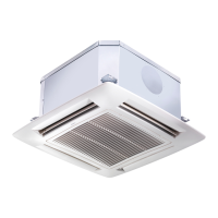
“Hydronic Global Cassette” Fan Coil Units
Fig.1.
A - Unit
B - Frame/Grille assembly
Fig.15.
- Heating: louvre position for correct air
ow.
- Cooling: louvre position for correct air
ow.
Warning
To close one or two air outlets use the special kit
Fig.18.
1 - Nut
2 - Wooden frame
3 - Threaded hangers
4 - Washers
5 - Nut
6 - Washers
7 - Threaded hangers
8 - Washers
9 - Nut
10 - Nut
Fig.19.
7 - Threaded hangers
11 - "T" bar (to be removed)
Fig.20.
7 - Threaded hangers
11 - "T" bar (to be removed)
12 - Suspension brackets
Fig.21.
13 - False ceiling
14 - Spirit level
Fig.24.
15 - Frame pre-hooking support
16 - Safety belt
17 - Frame xing screw
Fig.25.
- Gasket "A"
- Gasket "B"
-
Air discharge
Fig.26-27.
- Cold circuit water inlet
- Cold circuit water outlet
- Air purge valve
- Hot circuit water inlet
- Hot circuit water outlet
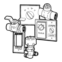
Legend
Fig.30.
- Ring nut
- O-ring
- Coil coupling
Fig.31
Automatic operation position
- Thermo-electric valve head
- Valve body
Fig.35.
18 - Capacitor
19 - Screw for ground connection
20 - Electronic board
21 - Power supply terminal board (available only on
models equipped with electric heaters)
22 - Auxiliary board
S - Power supply inlet
CV - Fan connector
CG - Float connector
CP - Pump connector
Fig.37-38.
24 - Power supply cable
25 - Terminal block
26 - Ground terminal
Fig.39-40.
X - Power supply cable way
(mod. 004 -008- 010)
Y - Power supply cable way
(mod. 012 -016- 020)
Fig. 41-42.
W - Route of power supply cable in the version with
electric heaters
(mod. 004E -008E- 010E)
Z - Route of power supply cable in the version with
heaters
(mod. 012E -016E- 020E)
Fig.43.
30 - Power supply cable (H07 RN-F)
31 - Thermostat cable
32 - Valve cables
Fig.44.
- Duct connection ange
- Clip
- 6 mm neoprene gasket
- Insulated exible duct
- Fresh air intake
- Conditioned air supply to an adjacent room
- Polystyrene partition
- Bae
- Frame
Fig.45.
Air intake grille
- Wall
- Undercut door
- Wall-tted grille
- Door-tted grille
Fig.46.
Winter operation diagram with fresh air intake
- Electrical box
- Antifreeze thermostat
- Speed controller
- Fresh air fan motor
- Relay 230V
Fig.47.
Diagram of conditioned air supply to an adjacent
room: one louvre closed
- Supply air duct to adjacent room
In case of two louvres closed, the fresh air ow
towards the adjacent room is 50% higher compared
with only one louvre closed (with equal static
external pressure)
Fig.50.
33 - Acrylic bre
 Loading...