28 42 GW...B
English
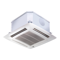
Installation of grille/frame assembly
See g. 24 - 25.
Carefully unpack the assembly and check for damage sustained in
transit.
Attach the assembly to the unit by using the two hooks.
Tighten the four xing screws, connect the two electric connectors and
insert the cables through the special cable xing hook.
Maintenance and owner's guide
Use the screws supplied to x the frame in position.
Ensure that the frame is not distorted by excessive tightening, that it is
aligned with the false ceiling and above all that there is a seal between
the air inlet and outlet.
In the drawing gasket "" prevents return air from mixing with the
supply air and gasket "" prevents the supply air from leaking into the
ceiling void.
On completion, the gap between the unit frame and the false ceiling
must not be more than 5 mm.
Maintenance
Cleaning and maintenance operations must be carried out by
specially trained personnel.
Before performing any service or maintenance operations, turn OFF
the main power switch.
To open the unit grille: (See g. 48).
Turn the two screws through 90° (1/4 turn).
Diagnostic
A green LED on the electronic board signals the dierent conditions:
Intermittent ashing LED – Normal operating conditions.•
Fixed LED – Float Alarm.•
Quick ashing LED – Temperature probe failure.•
Filter cleaning
Clean lters in accordance with the actual operating conditions and
times (approximately every 6 months).
The acrylic air lter is washable in water.•
Electrostatic and active carbon lters (which can be used on the
unit) are not washable but must be replaced.
(See g. 49).
Extract the lter
(See g. 50).
First vacuum clean the lter, then wash under tap water and nally dry.
Replace the lter in the correct position.
Prolonged shutdown:
Before starting the air conditioner:•
- clean or replace the unit air lters.
- check and clean the drain pan and the condensate discharge
of the unit
- check tightness of electric connections.
Additional maintenance
The electric panel is easily accessible by removing the cover panel. •
The inspection or replacement of internal components such as: fan
motor, coil, condensate discharge pump, oat switch, electric heater
(if tted), involve the removal of the condensate drain pan.
Condensate drain pan removal
During the removal operation of the condensate drain pan protect •
the oor with a plastic sheet under the unit.
Remove the frame-grille assembly by loosening the screws; drain the •
condensate water contained in the drain pan into a bucket of at least
10 litres capacity, using the special drain with a rubber plug.
Remove the electrical panel cover and disconnect the electric •
connections, connectors Cv, Cg, Cp and the yellow-green ground wire
(see drawing in “electrical connections” section). (See g. 51).
Remove the four xing screws on the side of the drain pan and •
carefully remove the condensate drain pan.
System drainage : If the system needs to be emptied, remember that
a water head always remains into the coil and it may freeze in case
temperature goes below 0° thus causing the heat exchanger failure.
The heat exchanger can be totally emptied by opening the valves and
blowing in air in each valve for 90 seconds at a minimum pressure of 6 bar.
Guide for the owner
When installation and tests are completed instruct the Owner on the
main operating modes of the air conditioner, such as:
Turning the unit ON and OFF.•
Changing the operation modes. •
Temperature selection.•
Leave the installation manual with the owner for future use during
maintenance operations or for any other needs.
 Loading...