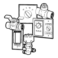
... any obstruction of the unit air intake or supply grilles (See g. 3).
... exposure to oil vapours (See g. 4).
... installation in areas with high frequency waves (See g. 5).
... ascending sections of condensate drain piping.
These may only be used near the unit with a maximum height
dierence of 200 mm from the top of the unit (See g. 6).
... horizontal sections or curves of condensate drain piping with less
than 2% slope (See g. 7).
... exposure to direct sunshine, when the unit is operating in the cooling
mode; always use shutters or shades.
... positions too close to heating sources which may damage the unit
(See g. 8).
... connecting condensate piping to sewage system drain without
appropriate trap.
Trap height must be calculated according to the unit discharge head in
order to allow sucient and continuous water evacuation
(See g. 9-10).
... only partial insulation of the piping.
Non-level installation which will cause condensate dripping
(See g. 11).
... attening or kinking the refrigerant pipes or condensate pipes (See
g. 12-13).
...slack on electrical connections (See g. 14).
See g. 15.
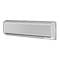
Install the unit as centrally as possible in the room, the air ow •
direction can be controlled by manually regulating the louvres
position, according to the operating mode (cooling or heating): this
will ensure optimum distribution of the air in the room.
During cooling mode operation the best position for the deecting •
louvres is one which allows air diusion close to the ceiling (Coanda
eect). In heating mode, the louvres should be positioned so that the
air is directed towards the oor, in order to prevent layers of hot air
forming in the upper part of the room.
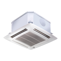
In order to allow easy and rapid installation and maintenance, make •
sure that in the selected position it is possible to remove the ceiling
panels or, if the ceiling is constructed of masonry, that access to the
unit is guaranteed.
ATTENTION:
Only restrict the air outlets as indicated in the drawing.
Prior to installation
It is advisable to place the unit as close as possible to the installation site
before removing it from the packaging.
The grille panel and the control are separately packed for maximum
protection (See g. 16).
IMPORTANT:
Do not lift the unit by the condensate drain discharge pipe; hold it
by its four corners only.
Unit installation will be facilitated using a stacker (See g. 16).
If plaster board ceiling panels are installed the maximum dimensions of
the unit housing must not exceed 660 x 660 mm (mod. 004 - 008 - 010)
and 900 x 900 mm (mod. 012 - 016 - 020).
In rooms with high humidity, brackets should be insulated by self
adhesive insulation supplied.
Installation
Mark the position of the hangers, connection lines and condensate
drain pipe, power supply cables and remote control cable (see
dimensions); the cardboard template (supplied with the kit) may be of
assistance for this operation.
Depending on the type of ceiling the hangers can be xed as shown in
the drawing 17.
Once the threaded hangers have been positioned, do not tighten the
nuts, and insert the washers as shown in the drawing 18.
First position the connection lines , as described in the chapter "Water
connections".
Remove the "T" bar in order to facilitate installation operations
(See g. 19).
Carefully lift the unit (without the frame) using the four suspension
brackets (or the four corners), inserting it into the false ceiling.
If the "T" bar cannot be removed the unit may need to be tilted (this
operation may only be carried out with false ceilings with a minimum
height of 300 mm) (See g. 20).
Align and level the unit by adjusting the nuts and locknuts on the
threaded hangers, maintaining a distance of 25 -30 mm between the
sheet metal body and the underside of the false ceiling.
Reposition the "T" bar and align the unit in relation to the bar by
tightening the nuts and locknuts.
After connection of the condensate drain line and the refrigerant lines,
carry out a nal check to make sure that the unit is level (See g. 21).
Condensate drain pipe
See g. 22 - 23.
To ensure correct condensate water ow, the drain pipe should have •
a gradient of 2% without obstructions. Furthermore an odour trap of
at least 50 mm depth should be made to prevent unpleasant odours
from reaching the room.
Condensate may be discharged at a maximum height of 200 mm •
above the unit, as long as the ascending tube is vertical and aligned
with the drainage ange.
If it is necessary to discharge the condensate from a level above 200 •
mm, install an auxiliary water discharge pump and oat valve.
A oat valve is recommended to stop the ow switch if there is a fault
at the auxiliary pump.
The condensate pipe must be insulated with a condensation-proof •
material such as polyurethane, propylene or neoprene of 5 to 10 mm
thickness. If more than one unit is installed in the room, the drain
system can be made as shown in the drawing.
Warnings: avoid
Installation
 Loading...