2. INDOOR UNIT INSTALLATION
GB-10
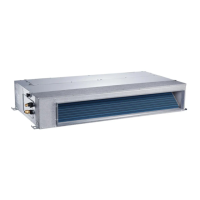
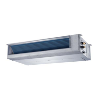
2.5 INSTALL THE DUCT
NOTE
Air inlet and air outlet should be apart far enough to ensure the performance of the unit.
When attaching a duct to the intake side, be sure also to attach an air filter (field supply)
Be sure to insulate the duct to prevent condensation from forming
Refer to the fan performance curve as below to select appropriate duct.
Canvas tie-in Canvas tie-in
Air outlet
Isolation booth
Isolation booth
Inspection opening
Air inlet
Air filter
Cover
Use the hanger rods to install the connecting duct instead of loading it directly onto the indoor unit.
Use nonflammable canvas tie-in to prevent vibration.
Ducted not exceeding 12000 Btu/h cooling capacity, the maximum allowable discharge duct length is less
than 1m.
If external resistance is too high (due to long extension of duct, for example), the air flow volume may
drop too low at each air outlet. Consult qualified engineer to increase the fan speed to increase the static
pressure corresponding to external resistance.
Unit with Pump
Open the cover of water supply intake by turning and pulling the cover.
Gradually insert about 2 liters of water into the indoor unit with stow tube.
Operate the unit under COOLING mode and check a drain pump pumping (a time lag of 1 minute is allowed
before water flowing out depending on the length of the drain pipe).
Check and confirm the water flows out through the drain hose.
Check the drain water drops at the end of the drain pipe.
Make sure there is no water leak at the drainage
Reassemble the cover of water supply intake.
Water supply intake
Unit with pump
CAUTION
Connect the duct supplied in the field.
2.5.1 Attach the duct and intake-side/outlet-side flange (field supply)
2.5.2 Connect the flange to the main unit with screws
2.5.3 Wrap the flange and duct connection area with aluminum tape or something similar to prevent air
escaping.
GB
 Loading...