Do you have a question about the Carrier 42WM 09C Series and is the answer not in the manual?
| Model | 42WM 09C Series |
|---|---|
| Cooling Capacity | 9000 BTU/h |
| Cooling Capacity (Ton) | 0.75 Ton |
| Compressor Type | Rotary |
| Refrigerant | R410A |
| Power Supply | 220-240V, 50Hz |
Instructions for proper handling, consultation, and storage of the manual.
Defines the intended use and limitations of the fan coil unit.
Emphasizes the importance of reading the manual before installation.
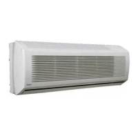
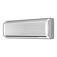
Details the primary parts of the fan coil unit casing, fan, motor, etc.
Explains the purpose and location of the unit's identification plate.
Covers how the appliance is packed and transported.
Provides detailed weight and dimension specifications for packed units.
Important safety and operational warnings for general use.
Critical safety measures related to electrical connections and voltage.
Essential safety rules for operating and maintaining the unit.
Outlines the operational parameters and limitations of the fan coil unit.
Guidelines for the proper disposal of the product and electronic waste.
Details the water inlet and outlet connections and their specifications.
Specifies requirements for optimal placement of the unit for performance and safety.
Step-by-step guide for the mechanical mounting of the unit.
Instructions for connecting to open water systems, including filtration.
Recommendations for installing the condensate drain pipe correctly.
Details the specifications and part numbers for the 3-way main battery valve.
Details the specifications and part numbers for the 2-way main coil valve.
Guidelines for safe and compliant electrical installation of the unit.
Instructions on how to route and connect electrical wires to the unit.
Describes the electrical components and protection of the EC motor.
Explains the different operating modes for the electrical heater.
Details signal inputs to the controller and impedance values.
Provides a key to understand the symbols and abbreviations used in diagrams.
Instructions for controlling multiple units from a single command source.
Diagram and component list for the main electronic control board.
Wiring diagram for a specific configuration (likely without valves/thermostat).
Wiring diagram for a 2-tube installation with valve and thermostat.
Wiring diagram for a 2-tube installation with thermostat and condensate pump.
How to adjust the vertical air louvers for optimal air direction.
How to adjust the horizontal air louvers for optimal air direction.
Instructions for using the remote control with single units.
Notes that fan coils cannot be networked.
Step-by-step guide for mounting the receiver unit.
Detailed diagram of the electronic board and its components.
Instructions for setting the unit's configuration using DIP switches.
Explains the function of the CF contact for window/presence detection.
Explains the function of the MP contact for condensate pump alarm.
Guide on how to insert batteries into the remote control.
Instructions for proper disposal of used batteries.
Table showing the meaning of different LED indicator states.
Step-by-step guide for configuring DIP switches on the unit.
How to send operational commands to the unit using the remote.
Instructions for turning off the appliance using the remote control.
Steps to set the time on the remote control and appliance.
How to send the set time information to the unit.
How to select the desired operating mode for temperature control.
How to send the set temperature to the unit.
How to choose fan speed (low, medium, high, auto) and transfer to unit.
Specifies operating parameters for cooling mode.
Specifies operating parameters for heating mode.
How the unit automatically selects heating or cooling based on temperature.
How to adjust the vertical air louvers for optimal air direction.
How to adjust the horizontal air louvers for optimal air direction.
How to turn the swing function on or off for air louvers.
Instructions on how to manually stop the flap's oscillation.
Steps to program the start time for the unit.
Steps to program the stop time for the unit.
Technical data and specifications for the electric heater models.
Information on the safety thermostats for the electric heater.
Details on manual and automatic reset safety thermostats and their function.
Warnings regarding fan operation and air outlet louvers during installation.
Lists and explains the function of various electrical components and terminals.
Provides detailed wiring diagrams for different unit configurations.
Visual representation of the electronic board with component labels.
Key to understand the symbols and acronyms used on the electronic board.
Explains the L1 operating mode where the resistance coil is the primary heating element.
Explains the L4 mode where resistance is used as a supplementary heating element.
Wiring diagram illustrating operation with resistance as the main heating element.
Wiring diagram illustrating operation with resistance as an integration element.
Illustrated guide for installing the condensate pump.
Instructions for installing the T2 probe for automatic heating/cooling switching.
Explains the operating logic with probe T2 and its technical specifications.
Procedures for cleaning the unit, fan, battery, and filter.
Guidelines for ordering replacement parts for the appliance.
Addresses problems related to the motor not rotating or rotating incorrectly.
Troubleshooting steps for units not heating or cooling effectively.
Guidance for resolving problems related to water leaks from the appliance.
Provides a table and formula for calculating water-side pressure drop.
Specifies operating parameters for cooling mode.
Specifies operating parameters for heating mode.
Table detailing airflow rates for various models and speeds.
Official statement of the product's compliance with EU directives and standards.