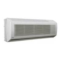
DISPLAYS OF THE INDOOR UNIT,
DISPLAYS OF THE INDOOR UNIT,
LED INDICATORS AND CONTROLS
LED INDICATORS AND CONTROLS
T : EMERGENCY and RESET button
S : Receiver of remote control signal
P : Green LED
R : Yellow LED
Q :Red LED
Indoor Unit LEDs
Information about the operating mode of the
indoor unit is given by the 3 LEDs (light-
emitting diodes) on the unit.
0 THE GREEN LEAD (P) indicates the
followings:
• Error diagnosis
• During normal operation, the LED is
illuminated.
NOTE
• When the unit is disconnected or in
Standby mode (waiting), the LED
remains switched off. If a breakdown
occurs, the LED flashes at 5-second
intervals. The error code is shown by
the number of times the LED flashes.
A pause of 5 seconds occurs between
the luminous signal cycles.
ERROR CODE DESCRIPTION
3 Ambient temperature sensor error
4 Indoor unit coil sensor error
7 Outdoor unit error
10 EEPROM malfunction
11 Corrupted serial number
12 Incomplete address/zone information
13 Gas flow distribution error
6

 Loading...