12
7 - POSITIONING AND INSTALLATION
Foresee appropriate damping devices in these fi xings to
ensure that noise and vibration transmission is avoided
(consult the reactions in the support in paragraph 7.5).
7.3 - Antivibrators assembly (silent-blocks)
Although the installer is the one who must decide on a case-by-
case basis the best way to place the unit in the ultimate location,
always in observation of the handling standards that have been
described, below is a proposed assembly sequence that may
facilitate the operation, keeping in mind that the sequence
performed in the installation shall be the one most suitable to the
solution chosen for each particular case based on the existence
(or lack thereof) of brick curb, type of silent-blocks used, etc.
In the event of assembling directly on silent-blocks to the ground,
it is recommended that a template of the unit’s footprint with the
anchoring points of the silent-blocks be made, as described in the
paragraph “Preparation of the ground”.
With the help of the crane or the forklift truck, the unit will be raised
to a suffi cient height that the silent-blocks can be screwed into its
base (see Chapter 5).
M12 metric threads have been provided for their placement in the
supports (consult the fi xing for antivibrators in paragraph 7.5). All
models will use M12 screws with a maximum length of 60 mm.
A hex key 19 or Allen wrench 10 will be used for this operation
based on the type of screw used.
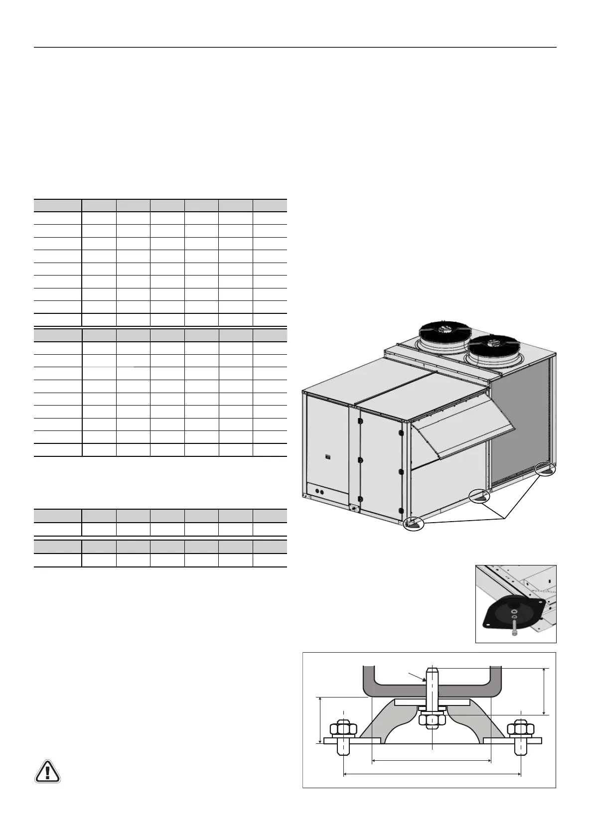
The optional silent-blocks that can be supplied for these units
must be placed perpendicular to the unit, as shown in the following
image.
Preparation of the ground
It is necessary to ensure that the surface where the unit is going
to be installed in completely fl at. Any defect in the preparation of
the unit support surface translates into stresses on the structure,
which may result in its deformation. The unit must be perfectly
level when installed.
These units can be installed on the fl oor or on a brick curb or
steel profi le. Based on the fi xing solution defi ned in the installation
project, it will be necessary to plan the placement in the base of
threaded rods in the expectation that the unit supports can be fi xed
later on. To do so, it is recommended that a template be made
with the heights corresponding to the fi xings.
Sound Level
These units are designed to work with a low acoustic level. In any
case, the following must be taken into account for the design of
the installation: the outdoor environment for acoustic radiation, the
type of building for the noise transmitted by air, the solid elements
for the transmission of vibrations.
To reduce transmission through solid surfaces to the maximum, it
is very advisable to install shock absorbers between the ground
or structure and the unit frame. If necessary, a study must be
commissioned to an acoustic technician.
Silent-blocks
The screws required for the installation of the silent-blocks are
not supplied from the factory.
These screws must have an adequate
quality to withstand the stresses to which
they will be subjected, and they must be
adapted to the installation site, either on a
brick curb or a steel profi le.
Note: If the silent-block hole has a diameter
greater than M12, a washer can be used to
adjust the size.
Max. 60 mm
M12
40 mm
72 mm
240 mm
Sound power level (LW)
Sound pressure level (LP)
Measurement conditions: in a clear fi eld, measured at a distance
of 5 metres, directivity 2 and at 1,5 metres from the ground.
Note: The sound pressure level depends on the installation conditions
and, as such, it only indicated as a guide. Values obtained according to
the ISO 3744 standard.
50FF/FC 100 110 120 130 145 160
63 Hz 64,6 65,1 65,6 66,1 66,6 66,9
125 Hz 71,4 71,9 72,4 72,9 73,4 73,7
250 Hz 77,9 78,4 78,9 79,4 79,9 80,2
500 Hz 80,2 80,7 81,2 81,7 82,2 82,5
1000 Hz 80,6 81,1 81,6 82,1 82,6 82,9
2000 Hz 78,1 78,6 79,1 79,6 80,1 80,4
4000 Hz 74,2 74,7 75,2 75,7 76,2 76,5
8000 Hz 69,4 69,9 70,4 70,9 71,4 71,7
Total dB(A) 86,0 86,5 87,0 87,5 88,0 88,3
50FF/FC 100 110 120 130 145 160
Total dB(A) 58,6 59,1 59,6 60,0 60,5 60,8
50FF/FC 170 180 200 220 250 280
Total dB(A) 61,0 60,7 61,5 62,7 64,0 65,0
50FF/FC 170 180 200 220 250 280
63 Hz 67,1 67,1 67,9 69,1 70,6 71,6
125 Hz 73,9 73,9 74,7 75,9 77,4 78,4
250 Hz 80,4 80,4 81,2 82,4 83,9 84,9
500 Hz 82,7 82,7 83,5 84,7 86,2 87,2
1000 Hz 83,1 83,1 83,9 85,1 86,6 87,6
2000 Hz 80,6 80,6 81,4 82,6 84,1 85,1
4000 Hz 76,7 76,7 77,5 78,7 80,2 81,2
8000 Hz 71,9 71,9 72,7 73,9 75,4 76,4
Total dB(A) 88,5 88,5 89,3 90,5 92,0 93,0

 Loading...


