85
C08002
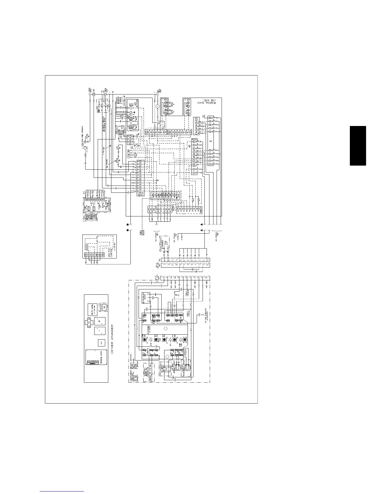
Fig. 26 -- 1--Stage Typical Wiring Diagram
NOTES:
Terminal board schematic layout does not match actual terminal board to simplify circuit traces. Ensure designated jumpers on terminal board are cut
when adding smoke detectors, phase loss relay and remote shutdown.
ECONOMIZER NOTES:
1. 620 ohm, 1 watt, 5% resister should be removed only when using differential enthalpy or dry bulb.
2. If a separate field---supplied 24V transformer is used for the IAQ sensor power supply, it cannot have the secondary of the transformer grounded.
3. For field ---installed remote minimum position POT, remove black wire jumper between P and P1 and set control minimum position POT to the
minimum position.
50TC

 Loading...